Yaskawa VS-626 MC5 User Manual
Page 135
Basic Operation
6.3.6 Speed Control (ASR) Structure
- 32
Fault Display
Remedy
Probable Cause
Tune Aborted
V/f Over Setting
(Displayed after completion of
Torque reference exceeded
100%, and no--load current
Rated voltage and rated fre-
quency settings are not cor-
rect.
Check the setting and correct any problems.
(Displayed after completion of
autotuning)
100%, and no--load current
exceeded 70%.
The load is connected to the
motor.
Disconnect the motor from the load.
6.3.6 Speed Control (ASR) Structure
D
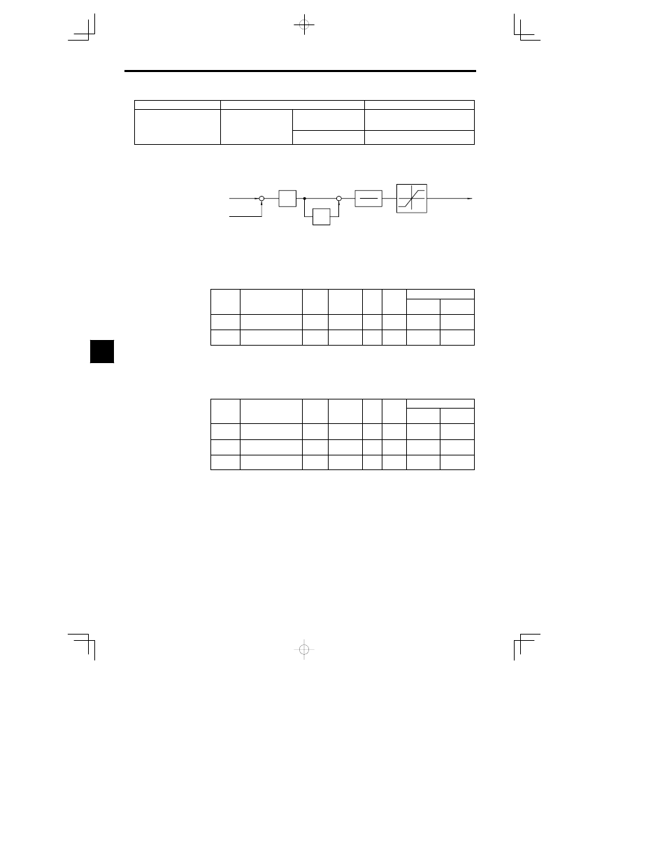
The following block diagram shows the structure of the speed control.
Frequency
reference
C5-01
,
C5-03
P
I
+
+
Torque limits
Secondary cur-
rent reference
C5-02
,
C5-04
C5-06
L7-01 to L7-04
Detected
speed
+
In vector flux control, the ASR’s P gain is the maximum frequency standard.
1
1
sT
Fig
6.12
Speed Control Structure
J
Gain Settings: C5-01, C5-02
D
Set the proportional gain and the integral time of the speed control (ASR).
User
Change
during
Setting
Factory
Valid Access Levels
User
Constant
Number
Name
during
Opera-
tion
Setting
Range
Unit
Factory
Setting
Open Loop
Vector
Flux Vector
C5-01
ASR proportional (P)
gain 1
0.00 to
300.00
Multi-
ple
20.00
B
C5-02
ASR integral (I) time 1
0.000 to
10.000
s
0.500
B
J
Low-speed Gain Settings: C5-03, C5-04, C5-07
D
Use these constants to set different proportional gain and integral time settings for low-speed opera-
tion. Constant C5-03 sets the low-speed proportional gain of the speed loop (ASR), and C5-04 sets the
low-speed integral time.
D
Set constant C5-07 to the frequency at which to switch to the low-speed ASR proportional gain and
integral time.
User
Change
during
Setting
Factory
Valid Access Levels
User
Constant
Number
Name
during
Opera-
tion
Setting
Range
Unit
Factory
Setting
Open Loop
Vector
Flux Vector
C5-03
ASR proportional (P)
gain 2
0.00 to
300.00
Multi-
ple
20.00
B
C5-04
ASR integral (I) time 2
0.000 to
10.000
s
0.500
B
C5-07
ASR switching frequen-
cy
0.0 to 400.0
Hz
0.0
A
6