Yaskawa VS-626 MC5 User Manual
Page 54
3.5
Wiring Control Circuit Terminals
- 21
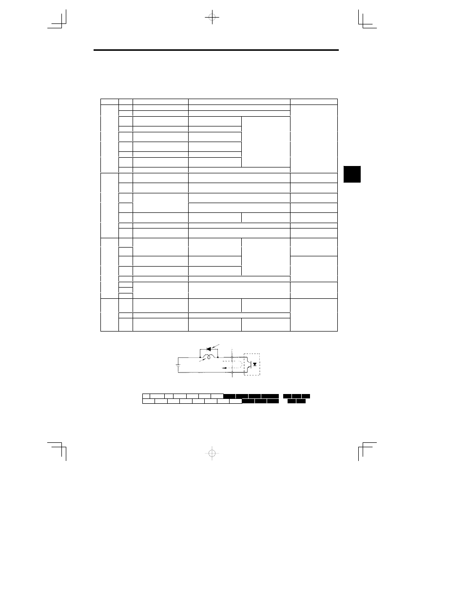
3.5.2 Control Circuit Terminal Functions
The functions of the control circuit terminals are shown in Table 3.9. Use the appropriate terminals for the
correct purposes.
Table
3.9
Control Circuit Terminals
Type
No.
Signal Name
Function
Signal Level
1
Forward run/stop command
Forward run when CLOSED; stopped when OPEN.
2
Reverse run/stop command
Reverse run when CLOSED; stopped when OPEN.
3
External fault input
Fault when CLOSED; normal
when OPEN.
S
4
Fault reset
Reset when CLOSED
Se-
quence
input
5
Multi-step speed reference 1
(Master/auxiliary switch)
Auxiliary frequency reference
when CLOSED.
Multi-function contact in-
puts
Command signals can be
24 VDC, 8 mA
Photocoupler isolation
input
signals
6
Multi-step speed reference 2
Multi-step setting 2 when
CLOSED.
Command signals can be
selected by setting H1-01 to
H1-06.
Photocoupler isolation
7
Jog frequency reference
Jog run when CLOSED.
H1-06.
8
External baseblock
Inverter output stopped when
CLOSED.
11
Sequence input common
15
15 V power output
15 V power supply for analog references
15 V
(Max. current: 20 mA)
33
--15 V power output
--15 V power supply for analog references
--15 V
(Max. current: 20 mA)
Analog
13
Master speed frequence refer-
--10 to 10 V/--100% to 100%
0 to 10 V/100%
--10 to 10 V (20 k ),
0 to 10 V (20 k )
Analog
input
signals
14
Master speed frequence refer-
ence
4 to 20 mA/100%, --10 to +10 V/--100% to 100%
0 to +10 V/100%
4 to 20 mA (250 )
g
16
Multi-function analog input
--10 to 10 V/--100% to 100%
0 to 10 V/100%
Auxiliary analog input
(H3-05)
--10 to 10 V (20 k ),
0 to 10 V (20 k )
17
Control common
12
Shield wire, optional ground
line connection point
9
Running signal (1NO contact)
Operating when CLOSED
Dry contacts
Contact capacity:
10
Running signal (1NO contact)
Operating when CLOSED.
M lti f
ti
t
t
Contact capacity:
1 A max. at 250 VAC
1 A max. at 30 VDC
Se-
quence
25
Zero speed detection
Zero level (b2-01) or below
when CLOSED
Multi-function outputs
Open-collector output
quence
output
signals
26
Speed agree detection
Within
r2 Hz of set frequency
when CLOSED.
Open-collector output
50 mA max. at 48 V*
signals
27
Open-collector output common
18
F
lt
h
CLOSED
18
d 20
Dry contacts
C
t
t
it
19
Fault output signal (SPDT)
Fault when CLOSED across 18 and 20
Fault when OPEN across 19 and 20
y
Contact capacity:
1 A max at 250 VAC
20
p
g
(
)
Fault when OPEN across 19 and 20
1 A max. at 250 VAC
1 A max. at 30 VDC
Analog
21
Frequency output
0 to 10 V/100% frequency
Multi-function analog moni-
tor 1
(H4-01, H4-02)
0 t
10 V
5%
Analog
output
i
l
22
Common
0 to 10 V max. 5%
2 mA max.
output
signals
23
Current monitor
5 V/Inverter’s rated current
Multi-function analog moni-
tor 2
(H4-04,H4-05)
2 mA max.
*
When driving an L load, such as a relay coil, always insert a flywheel diode as shown in Figure 3.18.
External power
:
48 V max.
Flywheel diode
Coil
50 mA max.
The rating of the flywheel diode
must be at least as high as the cir-
cuit voltage.
Fig
3.18
Flywheel Diode Connection
21
22
23
9
10
25
26
27
33
18
19
20
11
12(G)
1
2
3
4
5
6
7
8
13
14
15
16
17
Fig
3.19
Control Circuit Terminal Arrangement
3