Yaskawa VS-626 MC5 User Manual
Page 232
User Constants
8.2.6 Terminal Constants: H
- 24
J
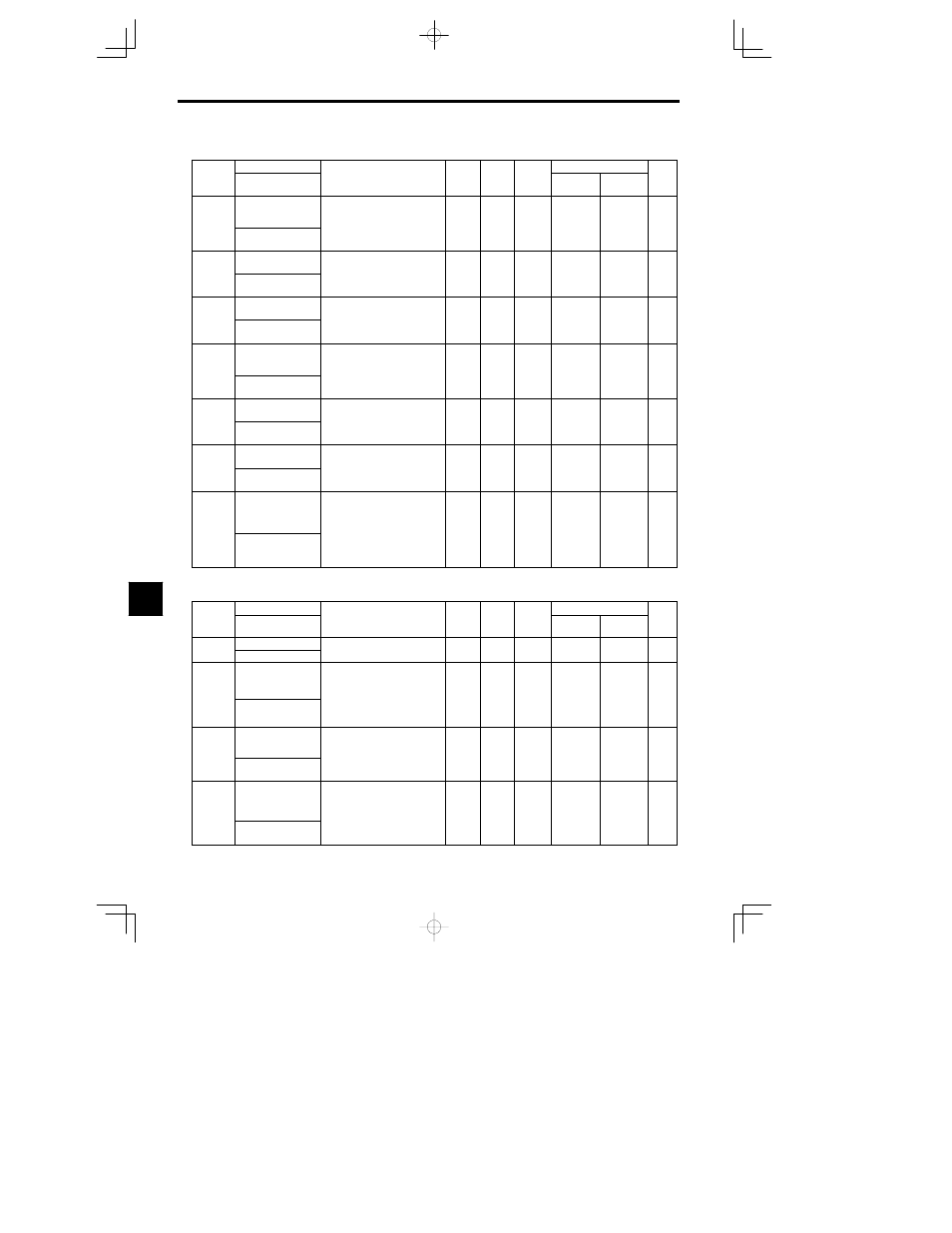
Analog Outputs: H4
Constant
Name
Setting
Factory
Change
during
Control Methods
Constant
Number
Display
Description
Setting
Range
Factory
Setting
g
during
Opera-
tion
Open Loop
Vector
Flux Vector
Page
H4-01
Monitor selection (ter-
minal 21)
Sets the number of the monitor item
to be output (U1-
) from termi-
nal 21.
4 10 11 12 13 14 25 28 can
1 to 33
2
B
B
- 46
H4 01
Terminal 21 Sel
4, 10, 11, 12, 13, 14, 25, 28 can-
not be set and 29 to 31 are not
used.
1 to 33
2
B
B
- 46
H4-02
Gain (terminal 21)
Sets the multi-function analog out-
put 1 voltage level gain.
S ts
h th r th monitor it m o t
0.00 to
1 00
B
B
46
H4-02
Terminal 21 Gain
Sets whether the monitor item out-
put will be output in multiples of 10
V.
0.00 to
2.50
1.00
B
B
- 46
H4-03
Bias (terminal 21)
Sets the multi-function analog out-
put 1 voltage level bias.
S ts o tp t ch r ct ristic p/do n
--10.0 to
0 0
B
B
46
H4-03
Terminal 21 Bias
Sets output characteristic up/down
parallel movement as a percentage
of 10 V.
--10.0 to
+10.0
0.0
B
B
- 46
H4-04
Monitor selection (ter-
minal 23)
Sets the number of the monitor item
to be output (U1-
) from termi-
nal 23.
4 10 11 12 13 14 25 28 can
1 to 33
3
B
B
- 46
H4 04
Terminal 23 Sel
4, 10, 11, 12, 13, 14, 25, 28 can-
not be set and 29 to 31 are not
used.
1 to 33
3
B
B
- 46
H4-05
Gain (terminal 23)
Sets the multi-function analog out-
put 2 voltage level gain.
S ts
h th r th monitor it m o t
0.00 to
0 50
B
B
46
H4-05
Terminal 23 Gain
Sets whether the monitor item out-
put will be output in multiples of 10
V.
0.00 to
2.50
0.50
B
B
- 46
H4-06
Bias (terminal 23)
Sets the multi-function analog out-
put 2 voltage level bias.
S ts o tp t ch r ct ristic p/do n
--10.0 to
0 0
B
B
46
H4-06
Terminal 23 Bias
Sets output characteristic up/down
parallel movement as a percentage
of 10 V.
--10.0 to
+10.0
0.0
B
B
- 46
H4-07
Analog output signal
level selection
Sets the signal output level for mul-
ti-function outputs 1 and 2 (termi-
nals 21, 23.)
0: 0 to +10 V output
1: 0 to +10 V output
0 1
0
B
B
- 46
H4 07
AO Level Select
1: 0 to +10 V output
The optional Analog Monitor
Card may also be used with this
setting.
0 1
0
B
B
- 46
J
MEMOBUS Communications: H5
Constant
Name
Setting
Factory
Change
during
Control Methods
Constant
Number
Display
Description
Setting
Range
Factory
Setting
g
during
Opera-
tion
Open Loop
Vector
Flux Vector
Page
H5-01
Station address
Set the Inverter’s node address
0 to 20
1
A
A
H5-01
Serial Comm Adr
Set the Inverter’s node address.
0 to 20
1
A
A
----
H5-02
Communication
speed selection
Set the baud rate for 6CN MEMO-
BUS communications.
0: 1200 bps
1: 2400 bps
0 to 3
1
A
A
----
H5 02
Serial Com Sel
1: 2400 bps
2: 4800 bps
3: 9600 bps
0 to 3
1
A
A
----
H5-03
Communication parity
selection
Set the parity for 6CN MEMOBUS
communications.
0: No parity
0 to 2
1
A
A
----
H5 03
Serial Com Sel
0: No parity
1: Even parity
2: Odd parity
0 to 2
1
A
A
----
H5-04
Stopping method af-
ter communication er-
ror
Set the stopping method for com-
munications errors.
0: Deceleration stop
1: Coast to stop
0 to 3
1
A
A
----
Serial Fault Sel
1: Coast to stop
2: Emergency stop
3: Continue operation
8