Yaskawa VS-626 MC5 User Manual
Page 234
User Constants
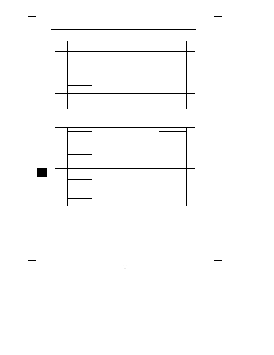
8.2.7 Protection Constants: L
- 26
Constant
Number
Page
Control Methods
Change
during
Opera-
tion
Factory
Setting
Setting
Range
Description
Name
Constant
Number
Page
Flux Vector
Open Loop
Vector
Change
during
Opera-
tion
Factory
Setting
Setting
Range
Description
Display
L2-04
Voltage recovery time
Sets the time required to return to
normal voltage at the completion of
a speed search, in units of one sec-
ond.
Set the time required for a 200 V
0.0 to
0 3
A
A
50
L2-04
PwrL V/F Ramp t
Set the time required for a 200 V
class Inverter to recover from 0
V to 200 VAC.
(For the 400 V class Inverter, the
time from 0 V to 400 VAC.)
0.0 to
5.0
0.3
A
A
- 50
L2-05
Undervoltage detec-
tion level
Sets the main circuit under voltage
(UV) detection level (main circuit
DC voltage) in V units.
Usually setting is not necessary.
150 to
210
190
*2
A
A
- 50
L2 05
PUV Det Level
Usually setting is not necessary.
Insert an AC reactor to lower the
main circuit undervoltage detec-
tion level.
0
*2
*2
A
A
- 50
L2-06
KEB deceleration rate
Restores the operating conditions
for momentary power loss by ap-
plying a frequency deceleration to
0.0 to
0 0
A
A
50
L2-06
KEB Frequency
plying a frequency deceleration to
create inertia energy when a power
loss occurs, and thus avoid the
power loss.
0.0 to
100.0
0.0
A
A
- 50
* 1. The factory setting depends upon the Inverter capacity. The values for a 200 V class Inverter of 0.4 kW are given. See page
- 35.
* 2. These are values for a 200 V class Inverter. Value for a 400 V class Inverter is double.
J
Stall Prevention: L3
Constant
Name
Setting
Factory
Change
during
Control Methods
Constant
Number
Display
Description
Setting
Range
Factory
Setting
g
during
Opera-
tion
Open Loop
Vector
Flux Vector
Page
L3-01
Stall prevention
selection during accel
0: Disabled (Acceleration as set.
With a heavy load, the motor
may stall.)
1: Enabled (Acceleration stopped
when L3-02 level is exceeded.
Acceleration starts again when
the current is returned )
0 to 2
1
B
- 51
L3 01
StallP Accel Sel
the current is returned.)
2: Intelligent acceleration mode
(Using the L3-02 level as a ba-
sis, acceleration is automatically
adjusted. Set acceleration time
is disregarded.)
0 to 2
1
B
- 51
L3-02
Stall prevention level
during accel
Effective when L3-01 is set to 1 or
2.
Set as a percentage of Inverter rated
current.
0 to 200
150
B
- 51
L3 02
StallP Accel Lvl
current.
Usually setting is not necessary.
The factory setting reduces the
set values when the motor stalls.
0 to 200
150
B
- 51
L3-03
Stall prevention limit
during accel
Sets the lower limit for stall preven-
tion during acceleration, as a per-
centage of the Inverter rated cur-
rent, when operation is in the fre-
b
th
i
0 to 100
50
A
- 52
L3 03
StallP CHP Lvl
,
p
quency range above the maximum
voltage frequency (E1-06.)
Usually setting is not necessary.
0 to 100
50
A
- 52
8