Yaskawa VS-626 MC5 User Manual
Page 19
1.1
Outline and Functions
- 3
1.1.2 Outline of Control Methods
The VS-626MC5 uses two control methods.
D
Open-loop vector control (factory setting)
D
Flux vector control
PG stands for pulse generator (encoder).
Vector control is a method for removing interference with magnetic flux and torque, and controlling torque
according to references.
Current vector control independently controls magnetic flux current and torque current by simultaneously
controlling the motor primary current and phases. This ensures smooth rotation, high torque, and accurate
speed/torque control at low speeds.
If the motor constants required for vector control are not known, the motor constants can be automatically
set with autotuning.
The control methods are effective for the following applications:
D
Open-loop vector control:
General variable-speed drive.
D
Flux vector control:
Simple servodrive, high-precision speed control/torque control.
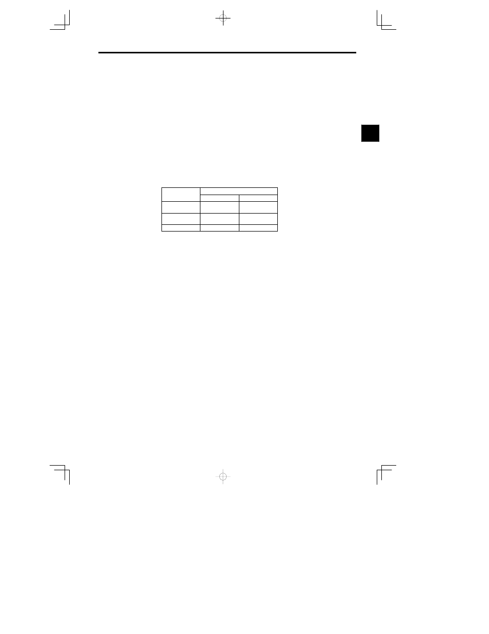
The control characteristics for each mode are shown in Table 1.2.
Table
1.2
Control Method Characteristics
Characteristic
Vector Control
Open-loop
Flux Vector
Speed Control
Range
1:100
1:1000
Speed Control
Precision
0.2 %
0.02 %
Initial Drive
150% at 1 Hz
150% at 0 r/min
1.1.3
Functions
J
Autotuning
Autotuning is effective for vector control. It solves problems in applicable motor restrictions and difficult
constant settings. The motor constants are automatically set by entering a value from the motor’s rating
nameplate.
Autotuning allows flux vector control to operate accurately with virtually any normal AC induction motor,
regardless of the supplier.
Always perform autotuning for motor unit separately before vector control operation.
J
Frequency References
The following five types of frequency references can be used to control the output frequency of the Invert-
er.
D
Numeric input from the Digital Operator
D
Voltage input within a range from 0 to 10 V
D
Voltage input within a range from 0 to
r10 V (with negative voltages, rotation is in the opposite direc-
tion from the run command.)
D
Current input within a range from 4 to 20 mA
D
Input from Option Card
Any of the above frequency references can be used by setting a constant.
A maximum of nine frequency references can be registered with the Inverter. With remote multi-step speed
reference inputs, the Inverter can operate in multi-step speed operation with a maximum of nine speed
steps.
J
Low Noise
The output transistor of the Inverter is an IGBT (insulated gate bipolar transistor). Using sine-wave PWM
with a high-frequency carrier, the motor does not generate metallic noise.
1