Yaskawa VS-626 MC5 User Manual
Page 122
6.2
Open-loop Vector Control
- 19
J
Acquisition of Motor Data
When autotuning motors for machine tool spindles, it is necessary to check the following data for the wind-
ing motors (Y-and - windings).
D
No-load voltage at base speed
D
Rated current at base speed
D
No-load frequency at base speed
D
Base speed(r/min)
D
Number of poles
D
No-load frequency at max. speed
D
No-load voltage at max. speed
D
Rated voltage (with 100% load)
D
Leakage inductance (L = L1 + L2)
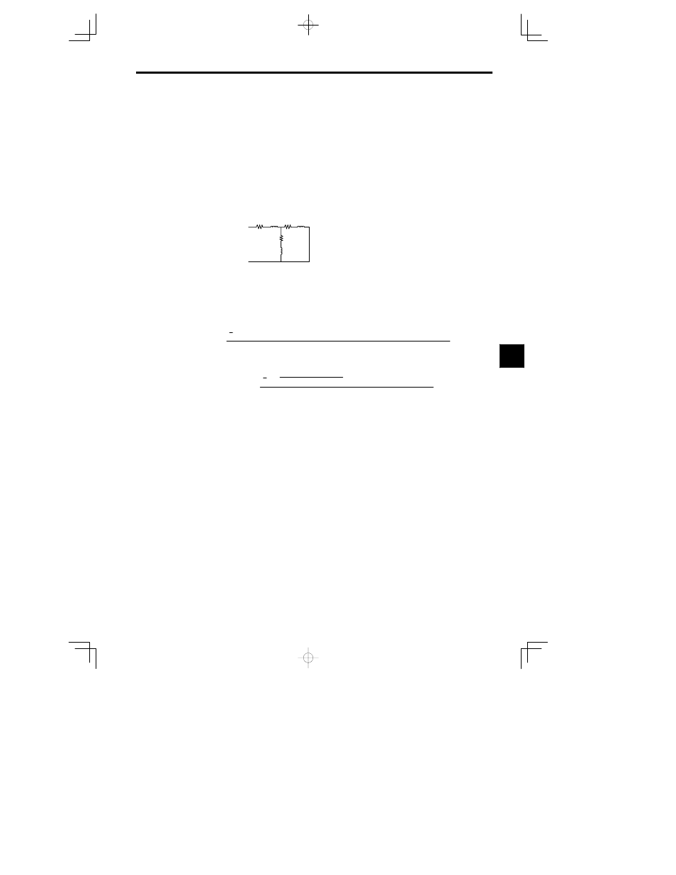
Refer to Fig. 6.8 for details.
L1
R1
R2/s
L2
Rm
Lm
R1
Primary resistance
R2
Secondary resistance
S
Slip
Rm Iron loss resistance
Lm
excitation inductance
Fig
6.8
Motor equivalent circuit (One phase, Example of Y-winding)
J
Constant setting prior to autotuning
Following constants must be set before performing autotuning.
D
Motor leak inductance (E2-06)
Set motor leak inductance using the following formula.
Setting by the motor leak inductance L (= L1 + L2)
(
E2
–
06
)
3
¯
2
Q Rated frequency at base speed (
Hz
)
L (
H
)
Rated current at base speed (
A
)
No–load voltage at base speed(
V
)
100
(
%
)
Note:Refer to Fig. 6.8 for details of leakage inductance
“
L”.
Setting by the lock test values
(E2–06)
3
¯ (Vs
2
3Is
2
)
(Ps3Is
2
)
2
¯
Rated current at base speed (A)
No–load voltage at base speed (V)
100(%)
Vs Lock test voltage V
Is
Lock test current A
Ps Lock test loss W
The result of the above formula should be from 5 to 25%. Verify the data when the obtained results are
too large (or small).
D
Carrier frequency
Set carrier frequency to 5.0 kHz.
Carrier frequency during autotuning: C8-30=1 (Carrier frequency is set to a value as set in C6-01)
Carrier frequency upper limit: C6-01=5.0 kHz
6