Yaskawa VS-626 MC5 User Manual
Page 228
User Constants
8.2.6 Terminal Constants: H
- 20
Constant
Number
Page
Control Methods
Change
during
Opera-
tion
Factory
Setting
Setting
Range
Display
Name
Constant
Number
Page
Flux Vector
Open Loop
Vector
Change
during
Opera-
tion
Factory
Setting
Setting
Range
Display
Name
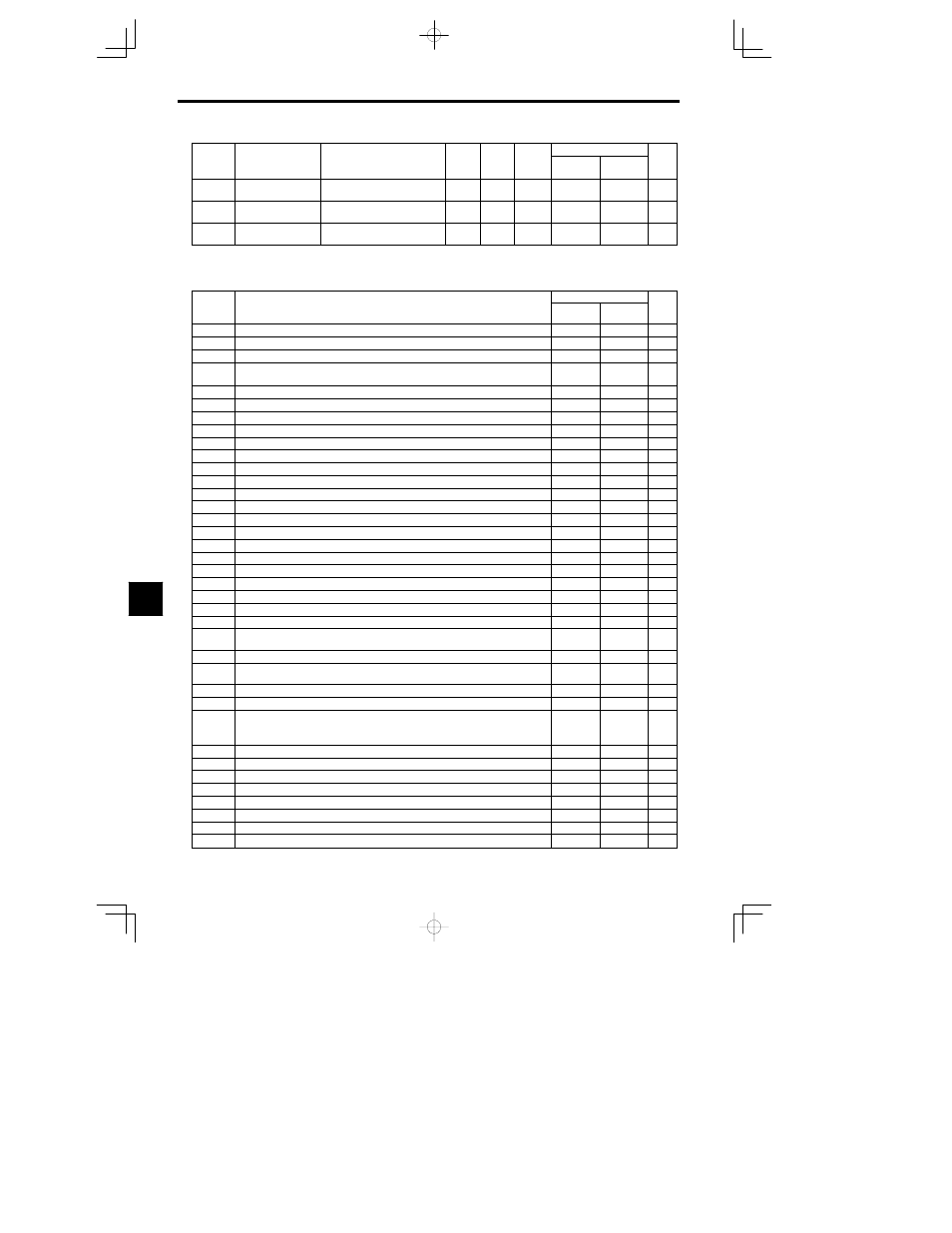
H1-04
Multi-function input 4
(terminal 6)
Terminal 6 Sel
0 to 77
4 (3) *
B
B
- 32
H1-05
Multi-function input 5
(terminal 7)
Terminal 7 Sel
0 to 77
6 (4) *
B
B
- 32
H1-06
Multi-function input 6
(terminal 8)
Terminal 8 Sel
0 to 77
8 (6) *
B
B
- 32
*
The values in parentheses indicate initial values when initialized in 3-wire sequence.
Multi-function Input Functions
Setting
Control Methods
Setting
value
Function
Open loop
Vector
Flux vector
Page
0
3-wire sequence (Forward/Reverse run command)
- 13
1
Local/Remote selection (ON: Operator, OFF: Constant setting)
- 32
2
Option/Inverter selection (ON: Option card)
- 32
3
Multi-step speed reference 1
When H3-05 is set to “0,” this function is combined with “Master/auxiliary speed switch.”
- 13
4
Multi-step speed reference 2
- 13
5
Multi-step speed reference 3
- 13
6
Jog frequency reference (higher priority than multi-step speed reference)
- 13
7
Accel/Decel time 1
- 16
8
External baseblock NO (NO contact: Baseblock at ON)
- 32
9
External baseblock NC (NC contact: Baseblock at OFF)
- 32
A
Accel/Decel ramp hold (ON: Accel/decel stopped, frequency on hold)
- 33
B
OH2 alarm signal input (ON: OH2 will be displayed)
- 33
C
Multi-function analog input selection (ON: Enable)
- 33
E
Speed control integral reset (ON: Integral control disabled)
- 33
F
Not used. (Do not input this setting.)
10
Up command (Always set with the down command)
- 34
11
Down command (Always set with the up command)
- 34
12
FJOG command (ON: Forward run at jog frequency d1-09)
- 16
13
RJOG command (ON: Reverse run at jog frequency d1-09)
- 16
14
Fault reset (Reset when turned ON)
- 35
15
Emergency stop (ON: Deceleration to stop in emergency stop time C1-09)
- 16
16
Motor switch command (Motor 2 selection)
- 35
1A
Accel/Decel time 2
- 16
1B
Constants write enable (ON: All constants can be written-in. OFF: All constants other than
frequency monitor are write protected.)
- 36
1C
Trim control increase (ON: d4-02 frequencies are added to analog frequency references.)
- 36
1D
Trim control decrease (ON: d4-02 frequencies are subtracted from analog frequency refer-
ences.)
- 36
1E
Analog frequency reference sample/hold
- 37
1F
Frequency reference terminal 13/14 selection (ON: selects terminal 14)
- 16
20 to 2F
External fault (Desired settings possible)
Input mode: NO contact/NC contact,
Detection mode: Normal/during operation
Stopping method: Deceleration to stop, coast to stop, emergency stop or continue operation.
- 37
60
DC injection braking command (ON: Performs DC injection braking)
- 40
61
External speed search command 1: Maximum output frequency (ON: speed search)
- 40
62
External speed search command 2: Set frequency (ON: speed search)
- 40
64
External speed search command 3
65
KEB (deceleration at momentary power loss) command (NO contact)
66
KEB (deceleration at momentary power loss) command (NO contact)
77
Speed control (ASR) proportional gain switch (ON: C5-03)
- 41
80
Winding change
- 67
8