4 wiring examples, 1 using a braking resistor unit, 2 using a braking unit and braking resistor unit – Yaskawa VS-626 MC5 User Manual
Page 277: Appendix
Appendix
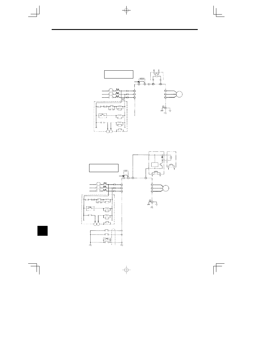
12.4.1 Using a Braking Resistor Unit
- 8
12.4 Wiring Examples
12.4.1 Using a Braking Resistor Unit
CIMR-MC5A20P4 to -MC5A27P5 (200 V class Inverters of 0.4 to 7.5 kW)
CIMR-MC5A40P4 to -MC5A4015 (400 V class Inverters of 0.4 to 15 kW)
Short-circuit bar
¨
1
DC Reactor to
improve input
power factor
(Optional)
Braking Resistor overheating contacts
(Thermal overload relay trip contacts)
Braking Resistor Unit
*3
VS-626MC5
MCCB
3-phase power
200 to 230 V
50/60 Hz
or
380 to 460 V
50/60 Hz
R
M
C
R (L1)
S
S (L2)
T
T (L3)
*1
400/200 V
THR
X
OFF
ON
M
C
SA
Overload relay trip contact
of Braking Resistor Unit
1
2
MC
TRX
TRX
20 18
Fault contacts
A sequence is required to turn
OFF the power supply for the
thermal overload relay trip con-
tacts of the Braking Resistor Unit.
¨
2
B1
B2
SA
SA
THR
X
U (T1)
V (T2)
W (T3)
Motor
IM
(200 V class Inverters: Ground
to 100
:
max., 400 V class In-
verters: Ground to 10
:
max.)
1
2
B
P
MC
©
*2
* 1
A transformer is not required for 200 V class Inverters.
* 2
Remove the short-circuit bar (normally connected) from between terminals
¨
1 and
¨
2 when connecting a DC Reactor (Optional).
* 3
Disable stall prevention during deceleration by setting L3-04 to “0” or “3”
when using a Braking Resistor Unit. The motor may not stop within the de-
celeration time if this setting is not changed.
12.4.2 Using a Braking Unit and Braking Resistor Unit
CIMR-MC5A2011 -MC5A2015 (200 V class Inverters of 11 kW 15 kW)
U (T1)
©
V (T2)
W (T3)
MCCB
R
MC
R (L1)
S
S (L2)
T
T (L3)
THRX
OFF
ON
MC
SA
Overload relay trip contact
of Braking Resistor Unit
1
2
MC
TRX
TRX
20 18
Fault contacts
SA
SA
THRX
3
Braking Unit
3
4
Motor
IM
(Ground to 100
:
max.)
¨
1
DC Reactor to
improve input
power factor
(Optional)
Braking Unit
(Optional)
¨
2
¨
3
¨
¨
0
P
B
Braking Resistor Unit
*2
(Optional)
1
2
Braking Resistor overheating contacts
(Thermal protector trip contacts)
Level
detector
3-phase power
200 to 230 V
50/60 Hz
3
4
VS-626MC5
©
MC
A sequence is required to turn
OFF the power supply for the ther-
mal overload relay trip contacts of
the Braking Resistor Unit.
*1
* 1
Remove the short-circuit bar (normally connected) from between termi-
nals
¨
1 and
¨
2 when connecting a DC Reactor (Optional).
* 2
Disable stall prevention during deceleration by setting L3-04 to “0” or “3”
when using a Braking Resistor Unit. The motor may not stop within the de-
celeration time if this setting is not changed.
Short-circuit bar
©
0
Forward Run/Stop
Forward run command
(forward run when closed)
Reverse Run/Stop
Reverse run command
(reverse run when closed)
External fault
12