Yaskawa VS-626 MC5 User Manual
Page 101
5.2
Trial Operation Procedures
- 7
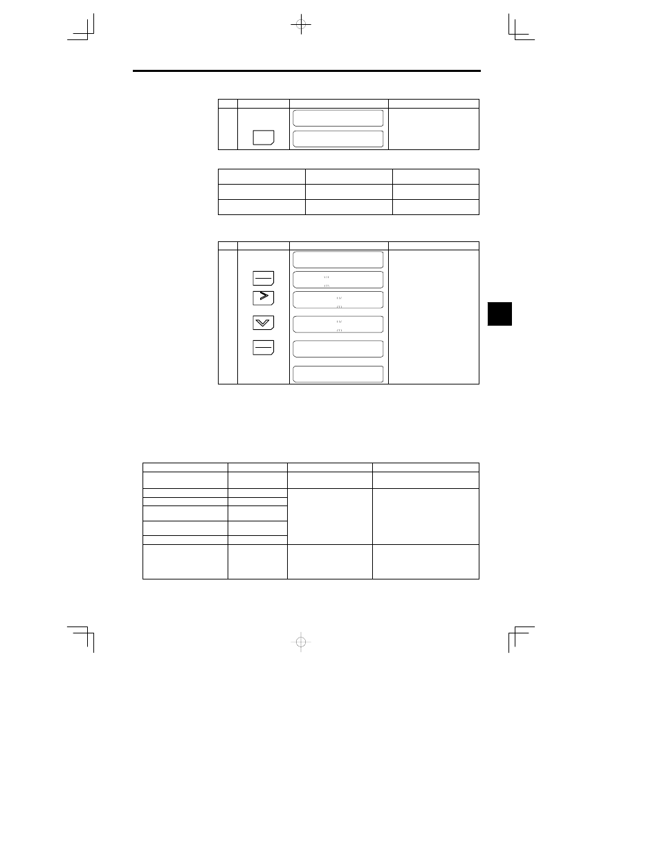
Step
Key Sequence
Digital Operator Display
Remarks
Tune Successful
Indicates the completion of autotun-
ing.
10
MENU
MC5
Main Menu
Operation
Returns to the operation mode dis-
play.
* 1. When the values displayed and the motor rated values differ, set each value separately.
* 2. There are differences between simple and advanced settings. Refer to the table below.
Operator Display
Simple Setting
(Motor nameplate)
Advanced Setting
Rated Voltage
Motor rated voltage
No--load voltage at rated revolu-
tions
Rated Frequency
Motor rated frequency
No--load frequency at rated revolu-
tions
Rated voltage for vector control motors is approx. 10 to 20% lower than general--purpose motors.
Always verify motor voltage listed on the nameplate or test report before use.
The following example procedure changes the motor rated current to 1.60 A.
Step
Key Sequence
Digital Operator Display
Remarks
Rated Current
1. 90 A
Displays the rated current.
1
DATA
ENTER
Rated Current
001. 90 A
When changing the set values, press
the DATA/ENTER Key and the digit
to change will blink.
2
Press 3 times
RESET
Rated Current
001. 90 A
Select the digit to be changed.
3
Press 3 times
Rated Current
001. 60 A
Set to 001.60 A.
4
DATA
ENTER
Entry Accepted
Press the DATA/ENTER Key to over-
write the set values. “Entry Accepted”
will be displayed for approximately
0.5 seconds.
Rated Current
1. 60 A
Returns to the rated current display.
D
When autotuning has been executed correctly, the constants (E1-04 to E2-09) will be automatically
written.
D
Use the following troubleshooting procedure is a fault occurs during autotuning.
J
Troubleshooting Autotuning Faults
The displays and countermeasures for autotuning faults are shown below in Table 5.1. If one of these faults
is detected, it will be displayed on the Operator and the motor will coast to a stop. The fault contact and
alarm contact outputs will not function. When a fault occurs, “Tune Aborted” will be displayed and the
messages shown in the following table will blink.
Table
5.1
Troubleshooting Autotuning Faults
Display Message
Fault
Description
Countermeasure
Data Invalid
Motor data fault
Motor data error for autotuning.
S Check the input data.
S Check the Inverter and motor capacities.
Resistance
Line resistance fault
No-load Current
No-load current fault
Saturation -1
Saturated core coeffi-
cient 1 fault
Autotuning was not completed
within a set time.
S Check the input data.
S Check the motor wiring
Saturation -2
Saturated core coeffi-
cient 2 fault
within a set time.
S Check the motor wiring.
Rated Slip
Rated slip fault
Accelerate
Acceleration fault
The motor did not accelerate with-
in a set time.
S Increase the acceleration time (C1-01).
S Increase the torque limits (L7-01, -02) if
these have been decreased.
S Disconnect the motor from the machine if
it has been connected.
5