Yaskawa VS-626 MC5 User Manual
Page 164
Advanced Operation
7.3.4 Option Constants: F
- 26
D
If the trim control increase command is ON when a frequency reference is input on the analog input,
the trim control level will be added to the analog frequency reference and then output as the output
frequency. If the trim control decrease command is ON, the frequency reference will be decreased by
the trim control level.
User
Change
during
Setting
Factory
Valid Access Levels
User
Constant
Number
Name
during
Opera-
tion
Setting
Range
Unit
Factory
Setting
Open Loop
Vector
Flux Vector
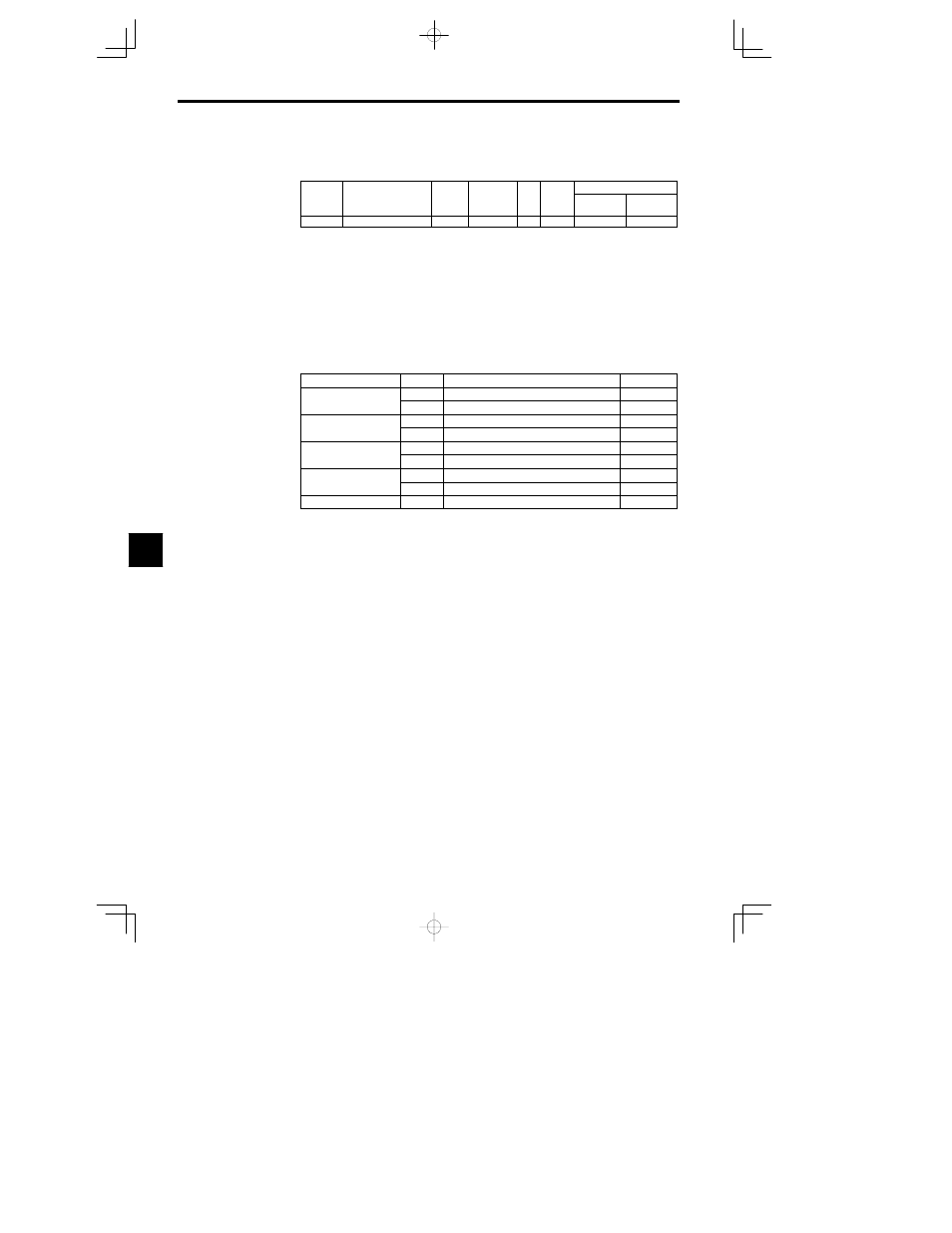
d4-02
+-- Speed limits
0 to 100
%
25
A
A
D
Set the trim control level as a percentage of the maximum output frequency.
D
If the frequency reference minus the trim control level is less than zero, the output frequency will be
zero.
D
Refer to the description of Multi--function Inputs (H1) for details on the trim control increase and trim
control decrease commands.
7.3.4 Option Constants: F
J
Installing Option Cards
A maximum of three Option Cards can be installed in the Inverter. The installation location of each is deter-
mined by the type of Card. Be sure to install the Cards in their correct locations.
Constants of the Option Cards can be referred or set with the access level Basic.
Table
7.4
Option Card Specifications
Type of card
Model
Specifications
Location
Analog Reference Card
AI-14U
14-bit analog, 2 inputs (voltage/current)
C
Analog Reference Card
AI-14B
14-bits analog, 3 inputs
C
Digital Reference Card
DI-08
8-bit digital input (BCD/binary)
C
Digital Reference Card
DI-16H2
16-bit digital input (BCD/binary)
C
PG Speed Control Card
PG-B2
Complementary, A/B-phase input
A
PG Speed Control Card
PG-X2
Line-driver, A/B-phase input
A
Analog Monitor Card
AO-08
8-bit analog output, 2 channels
D
Analog Monitor Card
AO-12
12-bit analog output, 2 channels
D
Pulse Monitor Card
PO-36F
Pulse frequency output
D
Installation Procedure
1. Turn OFF the Inverter’s main-circuit power supply. Wait at least one minute (or at least three minutes
for models of 30 kW or more).
2. Remove the Inverter’s front cover. Check to be sure that the CHARGE LED is turned OFF.
3. Check the Option Card’s installation location (A, C, or D). (See Figure 7.15.)
4. Insert the accessory spacer into the spacer mounting hole in the Inverter mounting base.
5. Align the Option Card connector with the connector position on the control board, and then pass the
spacer to the spacer mounting hole on the card.
Press firmly until the spacer snaps into place.
6. Connect the Option Card’s FG connection line to the Inverter ground terminal (terminal 12).
7