Yaskawa VS-626 MC5 User Manual
Page 248
Troubleshooting
9.1.1 Fault Detection
- 4
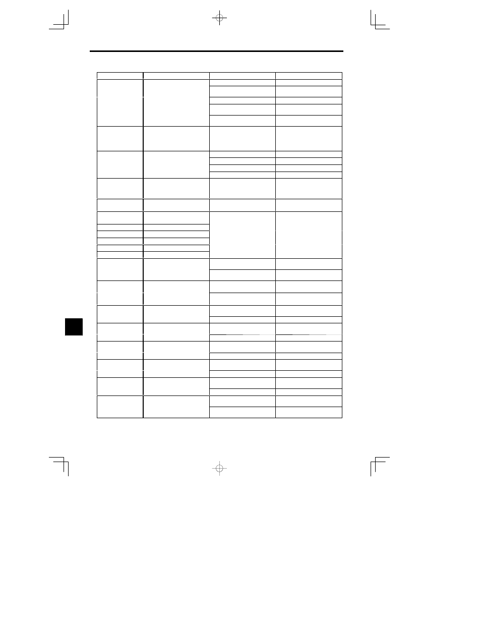
Corrective Actions
Probable Causes
Meaning
Fault Display
Excessive Speed Deviation
The load is too heavy.
Reduce the load.
The speed deviation has been greater
than the setting in F1-10 for longer
than the setting in F1-11.
The acceleration time and decelera-
tion time are too short.
Lengthen the acceleration time and
deceleration time.
DEV
S
d D
i i
than the setting in F1-11.
The load is locked.
Check the mechanical system.
Speed Deviation
The settings in F1-10 and F1-11
aren’t appropriate.
Check the settings in F1-10 and
F1-11.
-- --
Check for open circuit when using
brake (motor).
CF
Out of Control
Control Fault
The torque limit was reached contin-
uously for 3 seconds or longer during
a deceleration stop during open-loop
vector control.
-- --
Check the motor constants.
MC answerback error
H1 fault setting
Reset the constant setting.
MCANS
Anwerback signal is not received
within the time set by constant P1-03.
MC is not excited.
Excite the magnetic contactor.
Winding Change
within the time set by constant P1-03.
Winding change was not performed
Wiring is faulty.
Fix the wiring.
Winding change was not performed
properly.
Magnetic contactor is faulty.
Replace the magnetic contactor.
OPR
Oper Disconnect
Operator Connection Fault
The Operator was disconnected dur-
ing operation started by a run com-
mand from the Operator.
-- --
Check the Operator connection.
EFO
Opt External Flt
External fault input from Transmis-
sion Option Card.
-- --
Check the Trsansmission Option Card
and transmission signal.
EF3
External Fault 3
External fault (Input terminal 3)
EF4
External fault (Input terminal 4)
S Reset external fault inputs to the
lti f
ti
i
t
EF5
External fault (Input terminal 5)
An “external fault” was input from a
multi-function input.
p
multi-function inputs.
S Remove the cause of the external
EF6
External fault (Input terminal 6)
multi-function input.
S Remove the cause of the external
fault.
EF7
External fault (Input terminal 7)
EF8
External fault (Input terminal 8)
CPF00
Operator Communications Error 1
Communications with the Operator
bli h d
i hi 5
d
The Digital Operator’s connector isn’t
connected properly.
Disconnect the Digital Operator and
then connect it again.
COM-ERR (OP&INV)
Co
u cat o s w t t e Ope ato
were not established within 5 seconds
after the power was turned on.
The Inverter’s control circuits are
faulty.
Replace the Inverter.
CPF01
Operator Communications Error 2
After communications were estab-
lished there was a transmission error
The Digital Operator isn’t connected
properly.
Disconnect the Digital Operator and
then connect it again.
COM-ERR (OP&INV)
lished, there was a transmission error
with the Digital Operator for more
than 2 seconds.
The Inverter’s control circuits are
faulty.
Replace the Inverter.
CPF02
BB Circuit Err
Baseblock circuit error
-- --
Try turning the power supply off and
on again.
BB Circuit Err
The control circuit is damaged.
Replace the Inverter.
CPF03
EEPROM Error
EEPROM error
-- --
Try turning the power supply off and
on again.
EEPROM Error
The control circuit is damaged.
Replace the Inverter.
CPF04
Internal A/D Err
CPU internal A/D converter error
-- --
Try turning the power supply off and
on again.
Internal A/D Err
The control circuit is damaged.
Replace the Inverter.
CPF05
External A/D Err
CPU external A/D converter error
-- --
Try turning the power supply off and
on again.
External A/D Err
The control circuit is damaged.
Replace the Inverter.
CPF06
Option Error
Option Card connection error
The Option Card is not connected
properly.
Turn off the power and insert the Card
again.
Option Error
The Inverter or Option Card is faulty.
Replace the faulty component.
CPF20
Option Card A/D converter error
The Option Card is not connected
properly.
Turn off the power and insert the Card
again.
Option A/D Error
The Option Card’s A/D converter is
faulty.
Replace the Option Card.
9