Yaskawa VS-626 MC5 User Manual
Page 145
7.1
Open-loop Vector Control
- 7
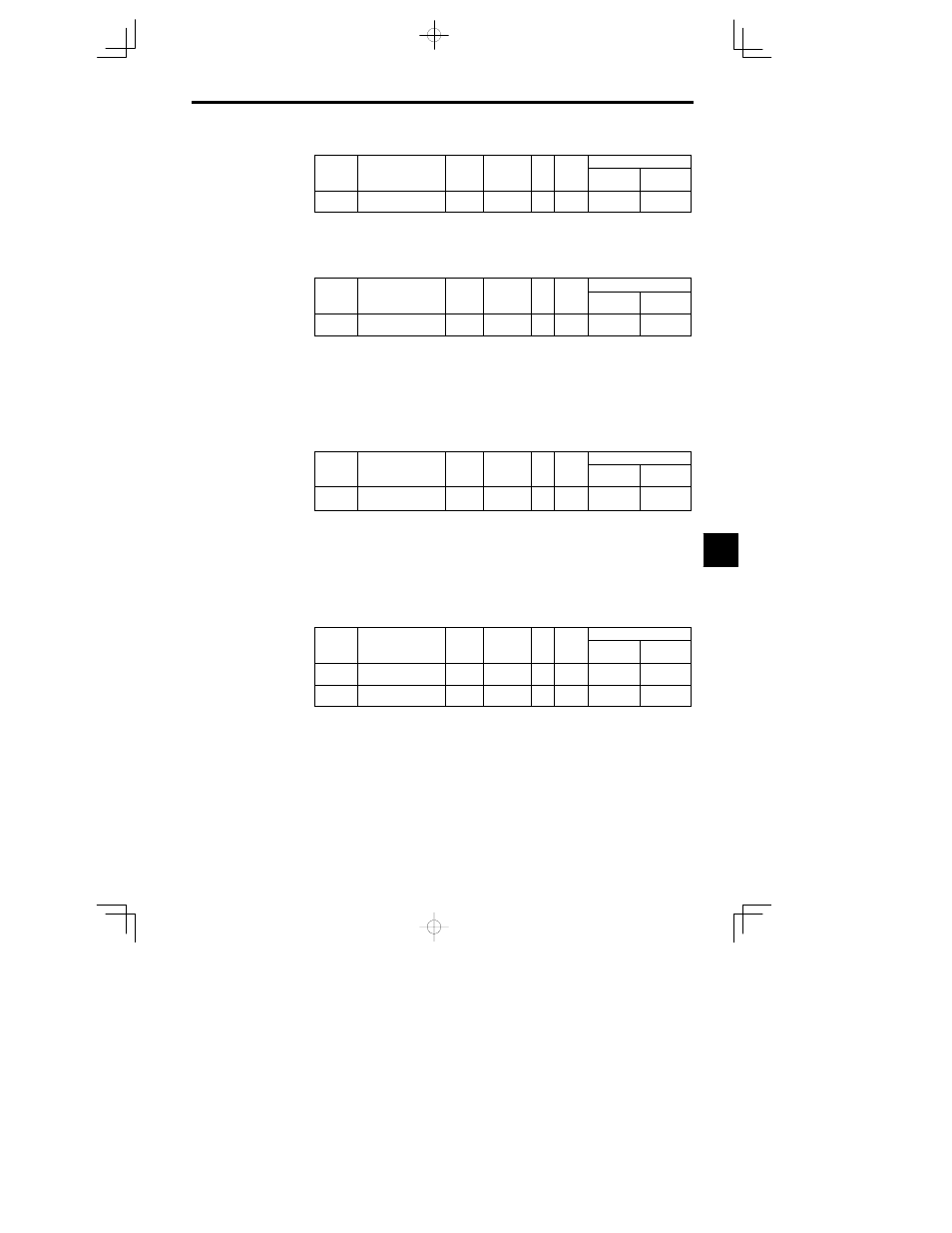
Motor No-load Current: E2-03
User
Change
during
Setting
Factory
Valid Access Levels
User
Constant
Number
Name
during
Opera-
tion
Setting
Range
Unit
Factory
Setting
Open Loop
Vector
Flux Vector
E2-03
(E5-03)
Motor no-load current
0.00 to
1500.0
A
1.20
Q
Q
D
The default setting depends upon the Inverter capacity.
(The table shows the default settings for 200 V class, 0.4 kW Inverters.)
D
Set the no-load current (E2-03) at the rated voltage and rated frequency. Normally this value isn’t
shown on the motor nameplate, so it might be necessary to contact the motor manufacturer.
Motor Line-to-line Resistance: E2-05
User
Change
during
Setting
Factory
Valid Access Levels
User
Constant
Number
Name
during
Opera-
tion
Setting
Range
Unit
Factory
Setting
Open Loop
Vector
Flux Vector
E2-05
(E5-05)
Motor line-to-line resist-
ance
0.000 to
65.000
9.842
A
A
D
The default setting depends upon the Inverter capacity.
(The table shows the default settings for 200 V class, 0.4 kW Inverters.)
D
Set the motor terminal resistance (U--V, V--W, and W--U) in constant E2-05. Normally this value isn’t
shown on the motor nameplate, so it might be necessary to contact the motor manufacturer for the ter-
minal resistance at the insulation class temperature. Use the following equations to calculate the resist-
ance value from the terminal resistance of a test report.
x
E-class insulation: Terminal resistance at 75
qC in the test report (:) x 0.92
x
B-class insulation: Terminal resistance at 75
qC in the test report (:) x 0.92
x
F-class insulation: Terminal resistance at 115
qC in the test report (:) x 0.87
Motor Leakage Inductance: E2-06
User
Change
during
Setting
Factory
Valid Access Levels
User
Constant
Number
Name
during
Opera-
tion
Setting
Range
Unit
Factory
Setting
Open Loop
Vector
Flux Vector
E2-06
(E5-06)
Motor leak inductance
0.0 to 30.0
%
18.2
A
A
D
The default setting depends upon the Inverter capacity.
(The table shows the default settings for 200 V class, 0.4 kW Inverters.)
D
Set the voltage drop (caused by the motor’s leakage inductance) as a percentage of the motor’s rated
voltage in constant E2-06.
D
This constant does not normally required setting because the Inverter automatically compensates dur-
ing operation.
D
Normally this value isn’t shown on the motor nameplate, so it might be necessary to contact the motor
manufacturer. It is also acceptable to set the loss (caused by the motor’s leakage inductance) as a per-
centage.
Motor Iron-core Saturation Coefficients 1, 2: E2-07, E2-08
User
Change
during
Setting
Factory
Valid Access Levels
User
Constant
Number
Name
during
Opera-
tion
Setting
Range
Unit
Factory
Setting
Open Loop
Vector
Flux Vector
E2-07
Motor iron-core satura-
tion coefficient 1
0.00 to 0.50
--
0.50
A
A
E2-08
Motor iron-core satura-
tion coefficient 2
0.00 to 0.75
--
0.75
A
A
D
Constants E2-07 and E2-08 are not required when using the motor at or below the rated frequency.
D
Set these constants when operating at a frequency higher that the motor’s rated frequency. Set the fol-
lowing values:
x
Motor iron-core saturation coefficient 1: Core-saturation coefficient when magnetic flux is 50%.
x
Motor iron-core saturation coefficient 2: Core-saturation coefficient when magnetic flux is 75%.
D
Normally these values aren’t shown on the motor nameplate, so it might be necessary to contact the
motor manufacturer. Operation will be possible with the factory-preset values.
7