400 v class – Yaskawa VS-626 MC5 User Manual
Page 44
3.4
Wiring Main Circuit Terminals
- 11
J
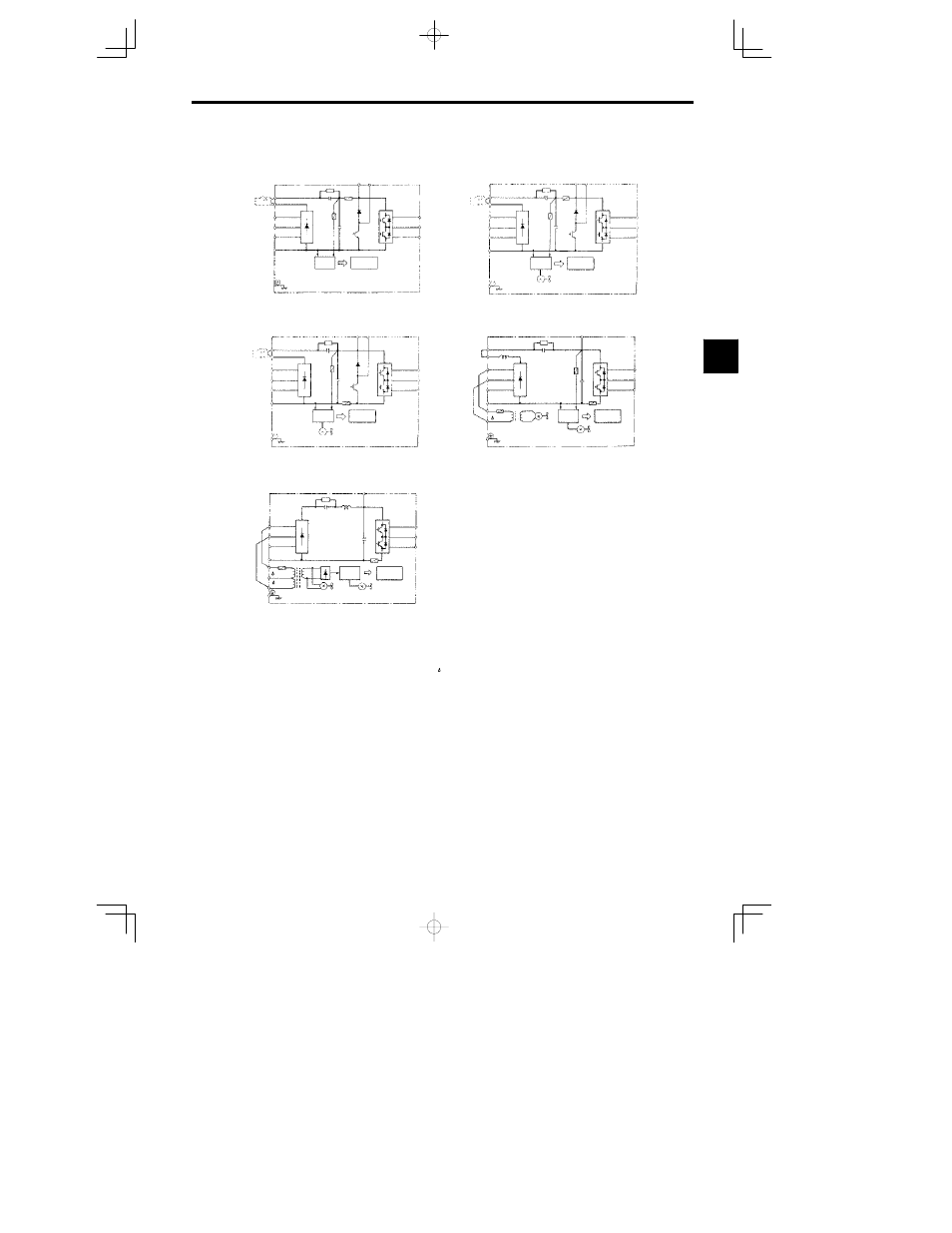
400 V Class
CIMR-MC5A40P4 to 41P5 0.4 to 1.5 kW
CIMR-MC5A4018 to 4045 18.5 to 45 kW
CIMR-MC5A42P2 to 43P7 2.2 3.7 kW
CIMR-MC5A4055 to 4075 55 75 kW
(DCL
option)
V(T2)
W(T3)
U(T1)
B2
B1
©
T(L3)
S(L2)
¨
2
¨
1
R(L1)
V(T2)
W(T3)
U(T1)
B2
B1
©
T(L3)
S(L2)
¨
2
¨
1
R(L1)
(DCL
option)
*
2
*
1
*
2
*
1
V
W
U
©
T
S
¨
2
¨
1
R
V
W
U
©
T
S
R
r
¨
3
r
200
400
¨
3
*
1
*
1
*
3
CIMR-MC5A45P5 to 4015 5.5 to 15 kW
V(T2)
W(T3)
U(T1)
B2
B1
©
T(L3)
S(L2)
¨
2
¨
1
R(L1)
(DCL
option)
*
2
*
1
Power
supply
(RCC)
Control
circuits
Power
supply
(RCC)
Control
circuits
Fin cooling fan
Power
supply
(RCC)
Control
circuits
Fin cooling fan
Power
supply
(RCC)
Control
circuits
Fin cooling fan
Internal
cooling fan
Power
supply
(RCC)
Fin cooling fan
Internal
cooling fan
Control
circuits
*
1 Prewired at the factory.
*
2 Remove the short-circuit bar from between
¨
1 and
¨
2 when connecting a DC
reactor to Inverters of 15 kW or less.
*
3 Prewired at the factory. When supplying power to the main circuits from the DC
power supply, remove the wiring from R-r and S- .
Fig
3.5
400 V Class Inverter Main Circuit Configurations
3
- Tag Generator (30 pages)
- MP3300iec (82 pages)
- 1000 Hz High Frequency (18 pages)
- 1000 Series (7 pages)
- PS-A10LB (39 pages)
- iQpump Micro User Manual (300 pages)
- 1000 Series Drive Option - Digital Input (30 pages)
- 1000 Series Drive Option - CANopen (39 pages)
- 1000 Series Drive Option - Analog Monitor (27 pages)
- 1000 Series Drive Option - CANopen Technical Manual (37 pages)
- 1000 Series Drive Option - CC-Link (38 pages)
- 1000 Series Drive Option - CC-Link Technical Manual (36 pages)
- 1000 Series Drive Option - DeviceNet (37 pages)
- 1000 Series Drive Option - DeviceNet Technical Manual (81 pages)
- 1000 Series Drive Option - MECHATROLINK-II (32 pages)
- 1000 Series Drive Option - Digital Output (31 pages)
- 1000 Series Drive Option - MECHATROLINK-II Technical Manual (41 pages)
- 1000 Series Drive Option - Profibus-DP (35 pages)
- AC Drive 1000-Series Option PG-RT3 Motor (36 pages)
- Z1000U HVAC MATRIX Drive Quick Start (378 pages)
- 1000 Series Operator Mounting Kit NEMA Type 4X (20 pages)
- 1000 Series Drive Option - Profibus-DP Technical Manual (44 pages)
- CopyUnitManager (38 pages)
- 1000 Series Option - JVOP-182 Remote LED (58 pages)
- 1000 Series Option - PG-X3 Line Driver (31 pages)
- SI-EN3 Technical Manual (68 pages)
- JVOP-181 (22 pages)
- JVOP-181 USB Copy Unit (2 pages)
- SI-EN3 (54 pages)
- SI-ET3 (49 pages)
- MECHATROLINK-III (35 pages)
- EtherNet/IP (50 pages)
- SI-EM3 (51 pages)
- 1000-Series Option PG-E3 Motor Encoder Feedback (33 pages)
- 1000-Series Option SI-EP3 PROFINET (56 pages)
- PROFINET (62 pages)
- AC Drive 1000-Series Option PG-RT3 Motor (45 pages)
- SI-EP3 PROFINET Technical Manual (53 pages)
- A1000 Drive Option - BACnet MS/TP (48 pages)
- 120 Series I/O Modules (308 pages)
- A1000 12-Pulse (92 pages)
- A1000 Drive Software Technical Manual (16 pages)
- A1000 Quick Start (2 pages)
- JUNMA Series AC SERVOMOTOR (1 page)
- A1000 Option DI-101 120 Vac Digital Input Option (24 pages)