Yaskawa MotionWorks IEC Hardware User Manual
Page 56
MotionWorks IEC Hardware Configuration – 2013-03-26
53
Step 6: When finished entering data blocks, Save the Configuration. This
will create the global memory I/O Group in the IEC Programming
Environment.
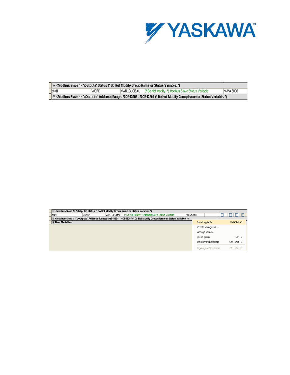
View of the Global Variables list. Click the Hardware tab in the Project Tree or use the 'View' menu to
access. Note the status variable has been created under an input section for this Modbus device even though no
input-type function codes were configured.
Step 7: Open the Global Variables list. Right click on the I/O group
header to “Insert Variable.” This variable can either be a BOOL, WORD, or
any other data type that fits the usage within the program. For example,
16 output bits can be defined as one WORD, and in the program, the 4th
bit can be accessed as follows: MYWORD.X3. Another example would be
16 individual BOOL variables with unique names.
Inserting a variable into the Modbus group.
The memory area for this Modbus device is shown in the Group
Heading. Bytes %QB43008 - %QB43207 are allocated for the Modbus
output registers. Enter the proper memory address for the Modbus
memory. If the first bit of the register QB43008 needs to be accessed,
enter %QX43008.0. If two bytes QB43008 and QB43009 need to be
accessed, it can be done using %QW43008 where W stands for WORD.