System cabling, Overview, Section 4 — system cabling – Grass Valley Karrera Video Production Center Installation v.4.1 User Manual
Page 61
KARRERA — Installation & Service Manual
61
Section
4
System Cabling
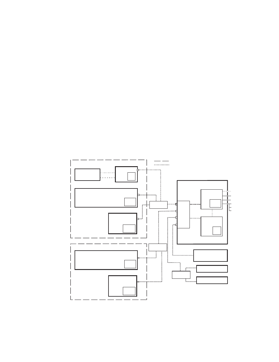
Overview
The Karrera system uses Ethernet, serial, VGA, and USB connections. The
Karrera Video Processor Frame has a built-in Ethernet switch. Tally outputs
and GPI I/O (General Purpose Interface Input/Output) control are also
available on the Karrera Frame (
).
Figure 34. Karrera System Communications Overview
CAUTION The facility network used for your Karrera system (and other video produc-
tion equipment) should be kept separate from any external network, to
prevent network traffic from adversely affecting Karrera system operation.
8623266_42_
r1_K
rr
Suite Boundary
Ethernet
Ethernet
(100m / 300ft max single hop length,
unlimited distance using switches)
Operator’s
Laptop
CD-ROM
Drive
Internal
Control
Video Processor Frame
Video
Processor
CPU
Compact
Flash
Image
Store
CPU
RAM
Only
Eh
te
rne
t Swi
tch
1
2
3
4
5
6
7
8
Menu
PC
Hard
Disk
Compact
Flash
Menu Panel
Karrera Control Panel, Suite 1
USB (2)*
Keyboard, VGA*
RS-232*
RS-422/485 (8)
GPI In/Out
Tally
USB
DVI-D
Operator’s
Laptop
CD-ROM
Drive
Compact
Flash
Karrera Control Panel, Suite 2
Ethernet LAN
Switch
Isolate Switcher System from External Network
Remote Aux Panel
Remote Aux Panel
Clip Store
Facility LAN
Switch
Ethernet LAN
Switch
Karrera Suite 1
Karrera Suite 2