Switcher tally configuration – Grass Valley Karrera Video Production Center Installation v.4.1 User Manual
Page 122
122
KARRERA — Installation & Service Manual
Section 5 — Basic Configuration
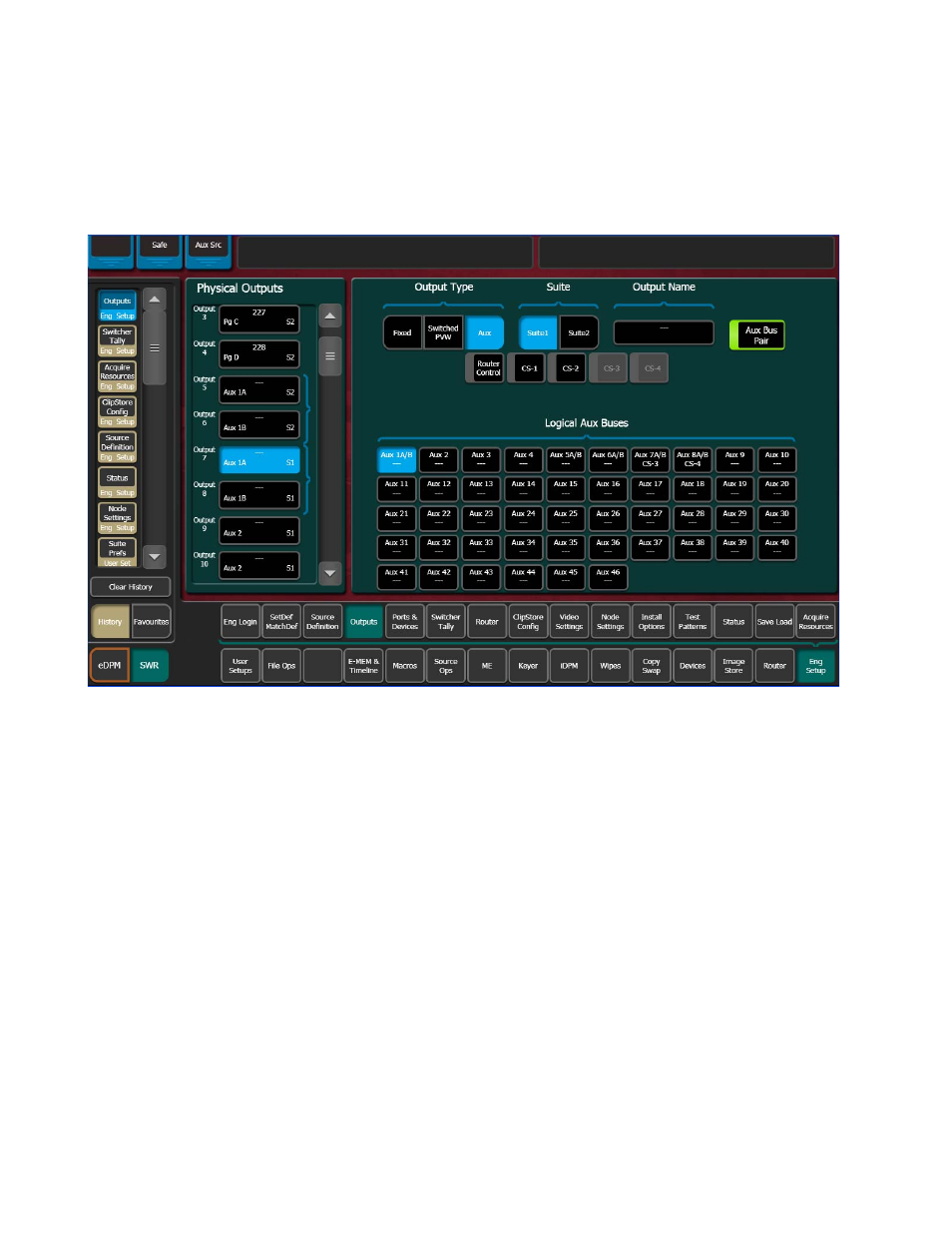
Aux Bus Pairs
Touching the
Aux Bus Pair
button configures the Aux Bus as an Aux Pair
(
).
Figure 75. Output Assignments Menu, Aux Bus Pair
Aux Pairs are two physical Aux Buses that have been configured to send a
video and associated key (or another video) signal. Pairing of the video and
key signal to be used on the Aux bus is defined in the Sources menu as
explained earlier. Aux pairs are indicated on the menu with a bracket
beside the two connector buttons. The Aux Bus pairs are also identified
with A and B letter indicators. The Aux A signal is always a video signal.
Switcher Tally Configuration
The Switcher Tally menus are used to configure tally system relays. These
menus include multiple tally calculators, three different tally calculation
methods, and user assignment of tally relays. The results of the tally calcu-
lators are applied to the tally relays on the GPI/Tally connectors on the rear
of the Karrera Video Processor Frame. Those relays can control external
tally lights. The Switcher Tally Menus also allow the user to map Engi-
neering Sources to the tally relays. Up to 96 tally relay outputs are available
on a Karrera Video Processor Frame, 24 for each installed Controller or ME
board. Tally is recalculated and refreshed every field.