Cluster management configuration example, Network requirements, Configuration procedure – H3C Technologies H3C S5120 Series Switches User Manual
Page 691
1-19
To do…
Use the command…
Remarks
Display members in a cluster
display cluster members
[ member-number | verbose ]
Clear NDP statistics
reset ndp statistics
[ interface interface-list ]
Available in user view
Cluster Management Configuration Example
Network requirements
z
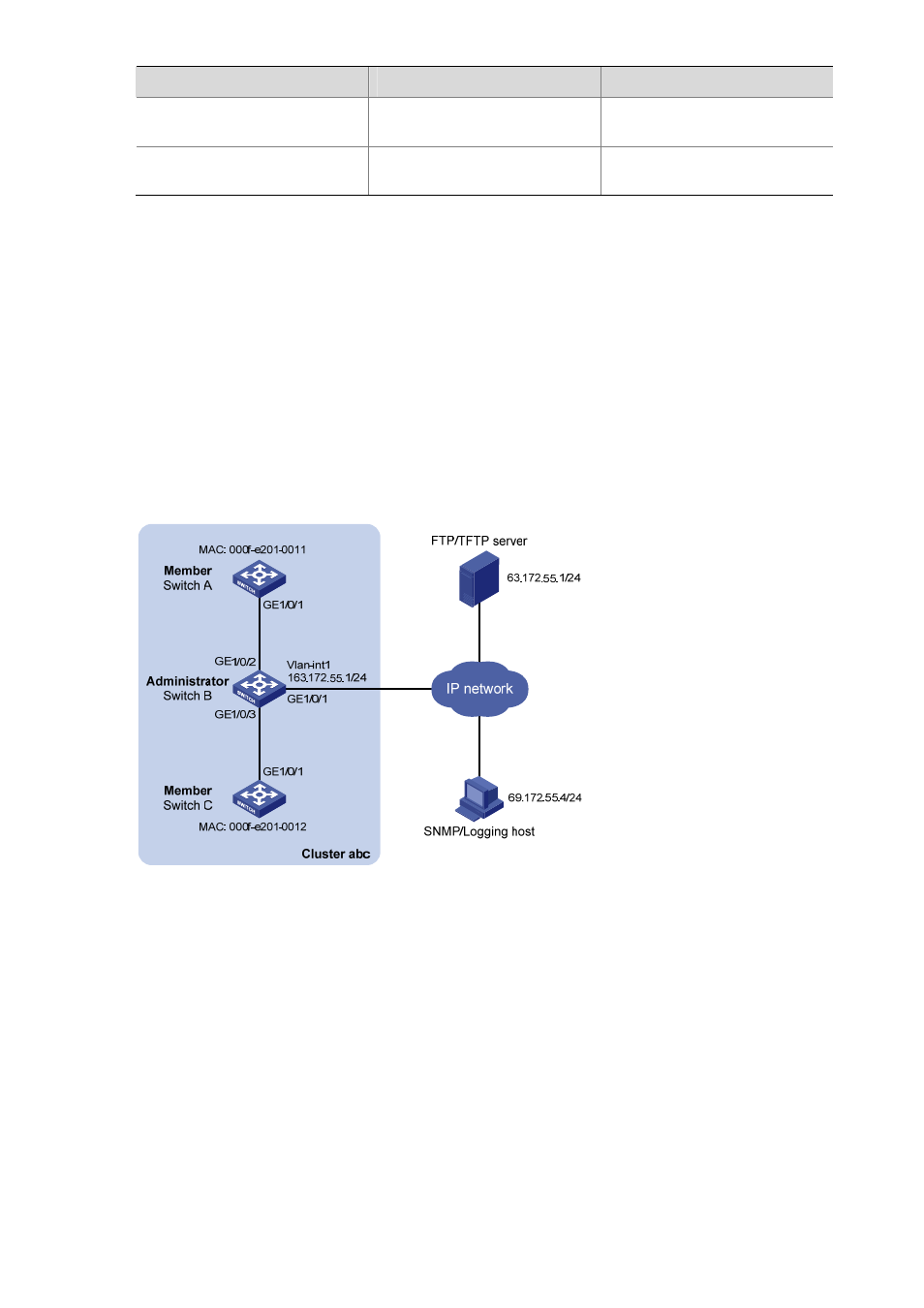
Three switches form cluster abc, whose management VLAN is VLAN 1. In the cluster, Switch B
serves as the management device (Administrator), whose network management interface is
VLAN-interface 1; Switch A and Switch C are the member devices (Member).
z
All the devices in the cluster use the same FTP server and TFTP server on host 63.172.55.1/24,
and use the same SNMP NMS and log services on host IP address: 69.172.55.4/24.
z
Add the device whose MAC address is 000f-e201-0013 to the blacklist.
Figure 1-4 Network diagram for cluster management configuration
Configuration procedure
1) Configure the member device Switch A
# Enable NDP globally and for port GigabitEthernet 1/0/1.
[SwitchA] ndp enable
[SwitchA] interface gigabitethernet 1/0/1
[SwitchA-GigabitEthernet1/0/1] ndp enable
[SwitchA-GigabitEthernet1/0/1] quit
# Enable NTDP globally and for port GigabitEthernet 1/0/1.
[SwitchA] ntdp enable
[SwitchA] interface gigabitethernet 1/0/1