Mstp configuration example, Network requirements – H3C Technologies H3C S5120 Series Switches User Manual
Page 204
1-39
To do...
Use the command...
Remarks
View the statistics of TC/TCN
BPDUs sent and received by all
ports in the specified MSTI or all
MSTIs
display stp
[ instance instance-id ] tc Available in any view
View the status information and
statistics information of MSTP
display stp
[ instance instance-id ]
[ interface interface-list ] [ brief ]
Available in any view
View the MST region
configuration information that has
taken effect
display stp region-configuration
Available in any view
View the root bridge information of
all MSTIs
display stp root
Available in any view
View the list of VLANs with VLAN
Ignore enabled
display stp ignored-vlan
Available in any view
Clear the statistics information of
MSTP
reset stp
[ interface interface-list ]
Available in user view
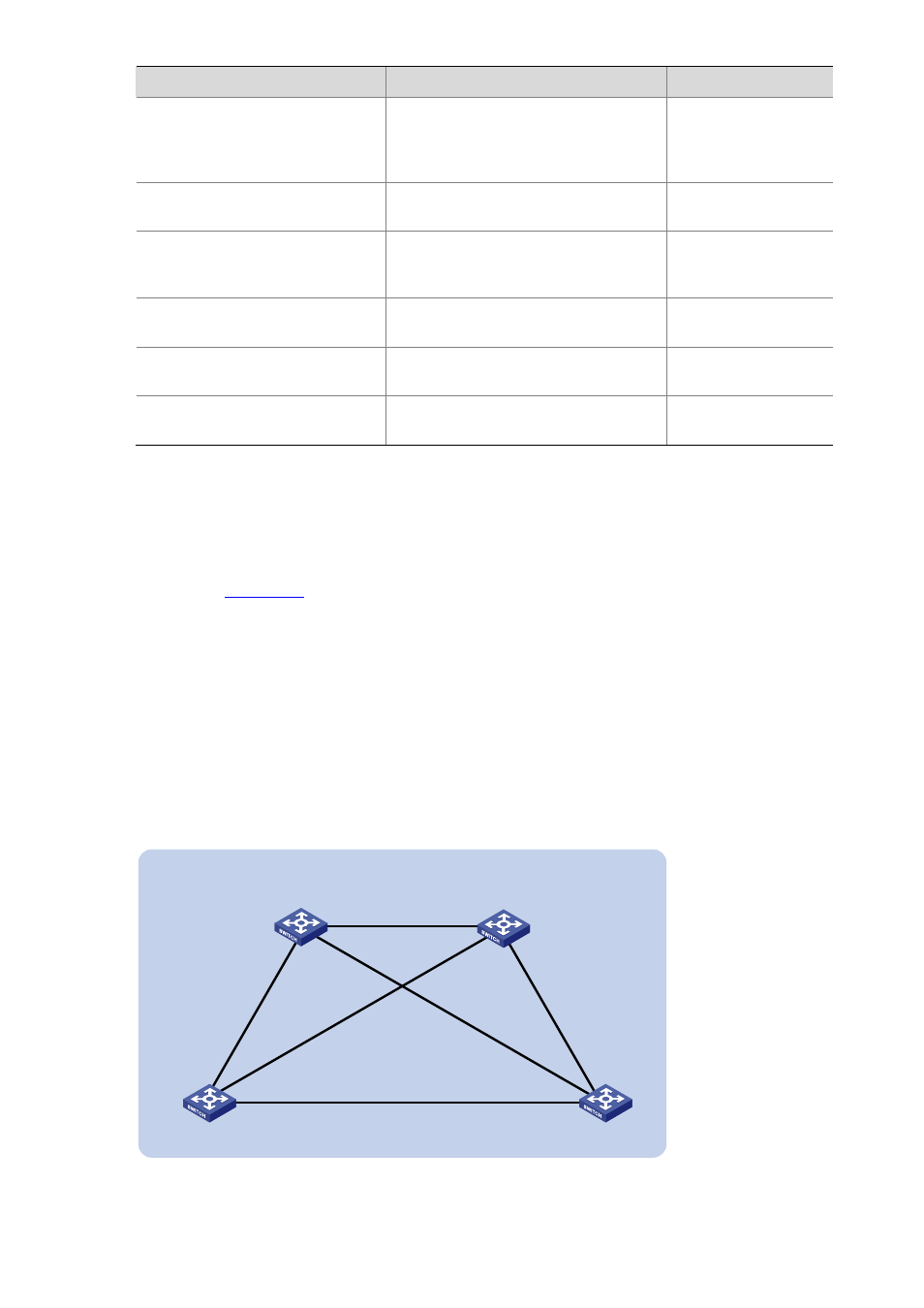
MSTP Configuration Example
Network requirements
As shown in
z
All devices on the network are in the same MST region. Device A and Device B work on the
distribution layer, while Device C and Device D work on the access layer.
z
Configure MSTP so that packets of different VLANs are forwarded along different spanning trees:
Packets of VLAN 10 are forwarded along MSTI 1, those of VLAN 20 are forwarded along MSTI 2,
those of VLAN 30 are forwarded along MSTI 3, and those of VLAN 40 are forwarded along MSTI 0.
z
VLAN 10 and VLAN 30 are terminated on the distribution layer devices, and VLAN 20 is terminated
on the access layer devices, so the root bridges of MSTI 1 and MSTI 3 are Device A and Device B
respectively, while the root bridge of MSTI 2 is Device C.
Figure 1-12
Network diagram for MSTP configuration
Permit: all VLAN
Per
mit:
VL
AN
30
, 40
Pe
rm
it:
V
LA
N
10
, 4
0
Permit: VLAN 20, 40
Permit: VLAN 30, 40
Permit: VLAN 10, 40
Device A
Device B
Device C
Device D
GE1/0/3
GE
1/0
/2
G
E
1/
0/
1
GE1/0/3
GE1
/0/2
G
E
1/0
/1
G
E
1/
0/
1
G
E
1/0
/1
GE1/0/3
GE1/0/3
GE1
/0/2
GE
1/0
/2
MST region