Port-based multicast vlan configuration, Network requirements, Configuration procedure – H3C Technologies H3C S10500 Series Switches User Manual
Page 88
73
Total 1 IP Group(s).
Total 1 IP Source(s).
Total 1 MAC Group(s).
Router port(s):total 1 port(s).
GE1/0/1 (D)
IP group(s):the following ip group(s) match to one mac group.
IP group address:224.1.1.1
(0.0.0.0, 224.1.1.1):
Host port(s):total 0 port(s).
MAC group(s):
MAC group address:0100-5e01-0101
Host port(s):total 0 port(s).
The output shows that IGMP snooping is maintaining the router port in the multicast VLAN (VLAN 10)
and the member ports in the sub-VLANs (VLAN 2 through VLAN 5).
Port-based multicast VLAN configuration
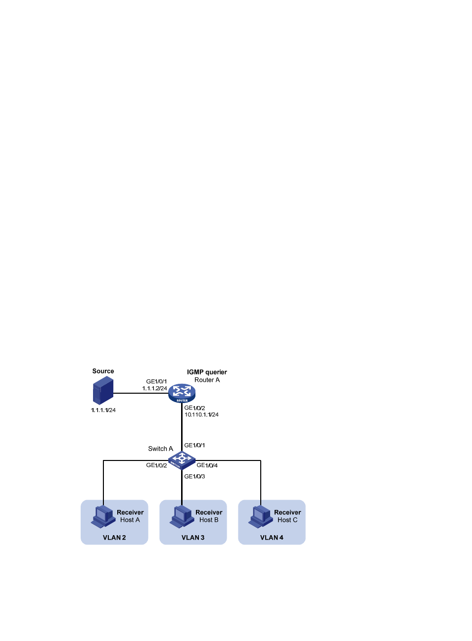
Network requirements
•
As shown in
, Router A connects to a multicast source (Source) through GigabitEthernet
1/0/1, and to Switch A through GigabitEthernet 1/0/2. IGMPv2 runs on Router A. IGMPv2
Snooping runs on Switch A. Router A acts as the IGMP querier.
•
The multicast source sends multicast data to multicast group 224.1.1.1. Host A, Host B, and Host C
are receivers of the multicast group, and the hosts belong to VLAN 2 through VLAN 4 respectively.
•
Configure the port-based multicast VLAN feature on Switch A so that Router A just sends multicast
data to Switch A through the multicast VLAN and Switch A forwards the multicast data to the
receivers that belong to different user VLANs.
Figure 25 Network diagram for port-based multicast VLAN configuration
Configuration procedure
1.
Configure IP addresses