Network diagram, Configuration procedure – H3C Technologies H3C S10500 Series Switches User Manual
Page 107
92
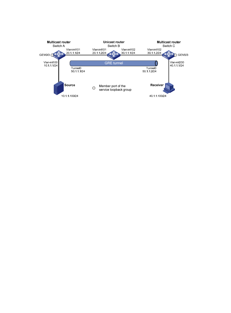
Network diagram
Figure 32 Network diagram for configuring multicast forwarding over a GRE tunnel
Configuration procedure
1.
Configure IP addresses
Configure the IP address and subnet mask for each interface as per
. (details not shown)
2.
Configure a GRE tunnel
# Create service loopback group 1 on Switch A and specify its service type as Tunnel.
[SwitchA] service-loopback group 1 type tunnel
# Disable STP and LLDP on interface GigabitEthernet 1/0/3 of Switch A, and add the interface to
service loopback group 1. GigabitEthernet 1/0/3 does not belong to VLAN 100 or VLAN 101.
[SwitchA] interface gigabitethernet 1/0/3
[SwitchA-GigabitEthernet1/0/3] undo stp enable
[SwitchA-GigabitEthernet1/0/3] undo lldp enable
[SwitchA-GigabitEthernet1/0/3] port service-loopback group 1
[SwitchA-GigabitEthernet1/0/3] quit
# Create Tunnel 0 on Switch A and configure the IP address and subnet mask for the interface.
[SwitchA] interface tunnel 0
[SwitchA-Tunnel0] ip address 50.1.1.1 24
# Configure Tunnel 0 on Switch A to work in the GRE tunnel mode and specify the source and destination
addresses for the interface.
[SwitchA-Tunnel0] tunnel-protocol gre
[SwitchA-Tunnel0] source 20.1.1.1
[SwitchA-Tunnel0] destination 30.1.1.2
[SwitchA-Tunnel0] quit
# Create service loopback group 1 on Switch C and specify its service type as Tunnel.
[SwitchC] service-loopback group 1 type tunnel
# Disable STP and LLDP on interface GigabitEthernet 1/0/3 of Switch C, and add the interface to
service loopback group 1. GigabitEthernet 1/0/3 does not belong to VLAN 200 or VLAN 102.
[SwitchC] interface gigabitethernet 1/0/3
[SwitchC-GigabitEthernet1/0/3] undo stp enable