Network diagram, Configuration procedure – H3C Technologies H3C S10500 Series Switches User Manual
Page 103
88
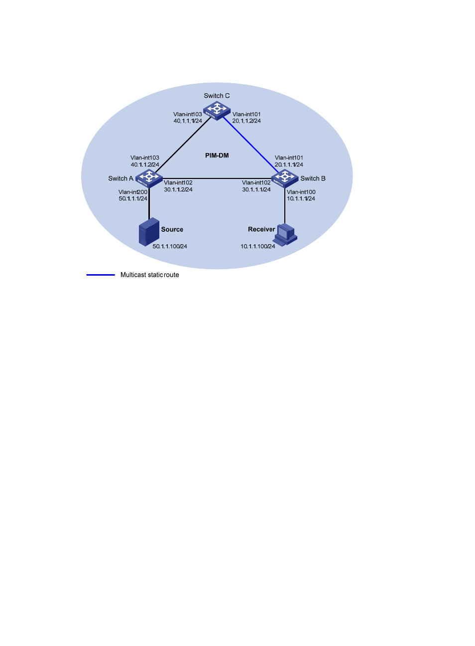
Network diagram
Figure 30 Network diagram for RPF route alternation configuration
Configuration procedure
1.
Configure IP addresses and unicast routing
Configure the IP address and subnet mask for each interface as per
. (details not shown)
Enable OSPF on the switches in the PIM-DM domain. Ensure the network-layer interoperation among the
switches in the PIM-DM domain. Ensure that the switches can dynamically update their routing
information by leveraging the unicast routing protocol. (details not shown)
2.
Enable IP multicast routing, and enable PIM-DM and IGMP
# Enable IP multicast routing on Switch B, enable PIM-DM on each interface, and enable IGMP on
VLAN-interface 100.
[SwitchB] multicast routing-enable
[SwitchB] interface vlan-interface 100
[SwitchB-Vlan-interface100] igmp enable
[SwitchB-Vlan-interface100] pim dm
[SwitchB-Vlan-interface100] quit
[SwitchB] interface vlan-interface 101
[SwitchB-Vlan-interface101] pim dm
[SwitchB-Vlan-interface101] quit
[SwitchB] interface vlan-interface 102
[SwitchB-Vlan-interface102] pim dm
[SwitchB-Vlan-interface102] quit
# Enable IP multicast routing on Switch A, and enable PIM-DM on each interface.
[SwitchA] multicast routing-enable
[SwitchA] interface vlan-interface 200