Shunt bcr bcr shunt shunt shunt – Measurement Computing WBK Options User Manual
Page 61
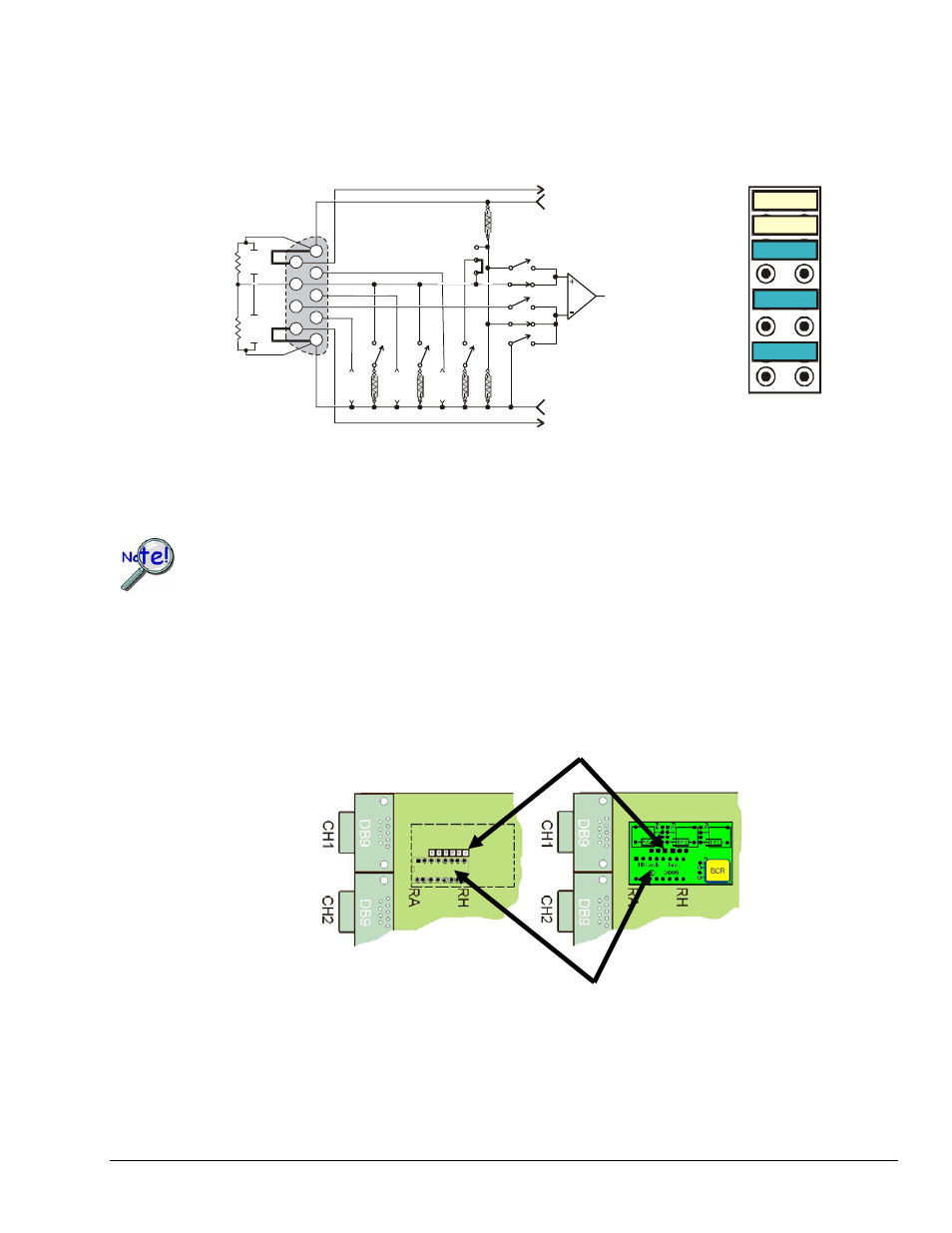
Note that the two half-bridges previously described are identical [circuit wise] to the one illustrated below,
which is being repeated from page 6.
The A thru H bridge-completion relations are the same, regardless of whether or not you choose to use a
CN-115-1 plug-in option. Refer to the configuration diagrams to set up your desired circuit(s).
Half-Bridge (+), Any Resistance from 60 to 1000 Ohms,
B,D, or F Shunt
IA
External
Bridge
DB-9
Input
Internal Bridge Completion
RA
RB
RC
RD
RE
RF
RG
RH
1
2
3
-Sense
+Sense
+Excitation
-Excitation
JN01
Switches
accessed
through
software
1
8
9
7
5
4
3
6
2
H
G
F
E
D
C
B
A
Shunt
BCR
BCR
Shunt
Shunt
Shunt
Half-Bridge Circuit Created by using the CN-115 Header Only, i.e., no plug-in card
If present, read the manufacturer’s data that applies to your resistors. Important soldering and
lead-bending information may be present.
CN-115-1 Mounting Orientation
When installing a CN-115-1 be careful to avoid bending the pins and ensure that the card is oriented in relation to
the DB9 connector as indicated below.
Jumper Pin Sections Must be Aligned
WBK16, Strain-Gage Module
949794
WBK16, pg. 21
No Card Installed Card Installed
The main Pins Must be Aligned with Corresponding Sockets
CN-115-1 Orientation, Shown for Channel 1