Connecting to the device interface side, Warning – Measurement Computing WBK Options User Manual
Page 177
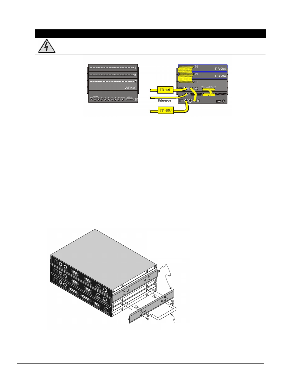
Connecting to the Device Interface Side –
WBK40 System Examples
WARNING
Electrical Shock Hazard! To avoid possible injury and equipment damage, turn off power to
devices and connected equipment prior to setup.
Channel Input Side Device Interface Side
A WaveBook/516E with a WBK40 and two DBK84 Modules
Note 1: Each DBK84 module requires a unique address setting as explained on page 13.
Device Interface Connections (seen in the above example):
1.
From the WBK40 P1 connector to two DBK84 Modules via two CA-37-1T cables.
(
P
2. From a WBK40 SYNC port to a WaveBook/516E SYNC Port via a CA-74-1 cable.
3. From a WaveBook/516E EXPANSION PORT to the WBK40 PARALLEL PORT
via a CA-35-12 cable.
4. From the WaveBook/516E ETHERNET port to the Ethernet via a CA-242 cable.
5. Power Supply – a TR-40U was connected to the POWER IN [DIN 5] connector to supply power
at +10 VDC to +30 VDC for the WBK40 and for the WaveBook/516E.
Using Fastener Panels to Stack Modules:
Fastener Panels, sometimes referred to as “splice plates” (p/n 262-0801 and p/n 232-0810) are
typically used to stack modules to WaveBooks, and/or other modules. Optional handles
(p/n HA-111) may also be attached to a system. The following figure illustrates the simplicity
of the mounting process.
Using Fastener Panels to Stack a WaveBook and two WBK Modules (use of the handle is optional)
Note:
When used with a WBK16, WaveBook/516, WaveBook/516A, or WaveBook/512A, fastener
panels will partially block the vents on the side of the module. This partial blocking of vents
does not jeopardize the cooling process.
DBK84
DBK84
WBK40
WaveBook/516E
Note 1
The fastener panels and associated screws are from
fastener panel kit p/n 262-0801 for connecting WBK
modules or p/n 232-0810 for connecting DBK84
modules.
Fastener Panels
The optional handle is p/n HA-111.
pg. 8, WBK40 & WBK41
926896
Thermocouple and Multifunctional Modules