Hardware setup, Configuration, Warning – Measurement Computing WBK Options User Manual
Page 35: Caution
WBK15, pg. 2
988396
WBK15, 5B Isolated Signal Conditioning Module
Hardware Setup
Configuration
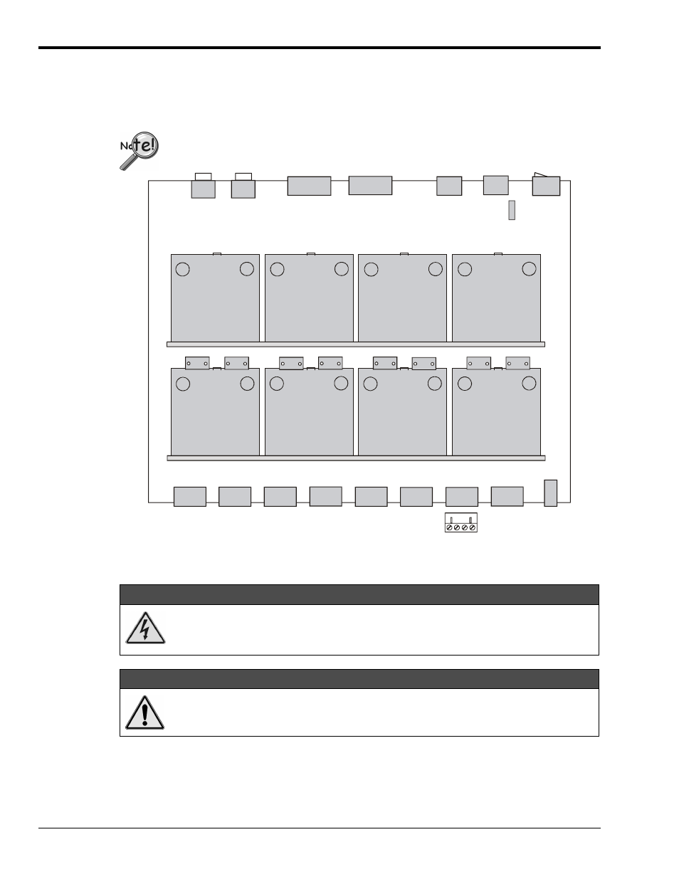
The next figure shows the board layout within a WBK15. Note the channel-number layout for the 5B
modules and the location for plug-in current-sense resistors.
Only current-input type modules require the plug-in resistors.
The plug-in resistors must be removed for all other module types.
CHANNEL 1
R10
ch 2
ch 1
ch 2
ch 3
ch 4
ch 5
ch 6
ch 7
ch 8
ch 1
ch 4
ch 3
ch 6
ch 5
ch 7
ch 8
CHANNEL 2
CHANNEL 4
R5
R16
R13
CHANNEL 3
CHANNEL 6
CHANNEL 5
R18
R20
CHANNEL 8
R22
R23
CHANNEL 7
Front Panel - signal inputs from 8 channels
Rear Panel
Expansion
Signal In
BNC
Expansion
Signal Out
BNC
DB15
Expansion
Control Out
DB15
Expansion
Control In
DIN5
Power
Out
DIN5
Power
In
ON/OFF
Switch
Fuse
Screw-terminal
Signal Plug
Status
LEDs
WBK15 Board Layout
Installation of 5B Modules
WARNING
WARNING
WARNING
WARNING
Electric shock hazard! Turn off power to WBK15 and all connected modules and
devices before inserting or removing modules. Failure to do so could lead to injury or
death due to electric shock.
CAUTION
CAUTION
CAUTION
CAUTION
Handle the 5B module carefully while inserting pins into the daughterboard. Do not
over-tighten mounting screw.
The 5B modules plug into a daughterboard (×2) on WBK15’s motherboard. Rubber bumpers on one side
and a tilted daughterboard allow the module to rest at a 5° angle to facilitate insertion and removal. The
adjacent daughterboard has a cut-a-way to allow room for a screwdriver (see figure).