Measurement Computing WBK Options User Manual
Page 137
1. If you have not already done so, turn OFF the power to, and UNPLUG the WBK18 module and
all connected equipment. Remove all signal I/O lines from the unit.
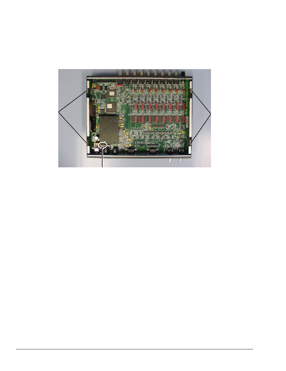
2. Using a Phillips screwdriver, remove the four Cover Plate Screws from the left and right sides
of the unit. The following figure points out the screw locations.
3. Remove the Cover Plate [not shown].
F900
F900 Fuse Location in a WBK18 Module
Cover Plate
Screw Locations
Cover Plate
Screw Locations
4. Locate the F900 fuse. It is located near the rear panel edge, close to the DIN5 POWER IN connector.
5. While wearing a grounded wrist strap, remove and replace the bad fuse. Ensure that the new fuse is fully
seated.
6. Replace the Cover Plate and secure it to the chassis with the 4 screws that were removed in step 2.
7. Return the WBK18 module to normal service. Should any problems be noted, consult the factory.
WBK18, pg. 22
926896
WBK18, Dynamic Signal Input Module