Gain of 8-pole filter mode – Measurement Computing WBK Options User Manual
Page 125
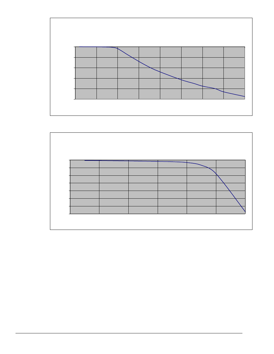
Gain of 8-pole Filter Mode
-100
-80
-60
-40
-20
0
0
0.5
1
1.5
2
2.5
3
3.5
4
FIN/FC
Gain (dB)
Gain of 8-pole Filter Mode
-14
-12
-10
-8
-6
-4
-2
0
0
0.2
0.4
0.6
0.8
1
1.2
Gain (dB)
FIN/FC, Zoom-In to Filter Cutoff Frequency Region
As described above, aliasing results from the relationship between input frequency and sampling
frequency. Configuring the filter correctly serves to attenuate undesired frequencies. However, thought
must also be given to the sampling rate of the A/D converter. In general, for alias considerations, the
sampling rate should be set as high as possible, given the number of active channels being used. Recall
that the maximum sampling rate is 1 MHz/(n +1) where n is the number of active channels. Because the
sampling rate determines the frequency at which aliasing occurs, it determines the input signal bandwidth,
for a given level of alias rejection. This relationship is shown in the following example.
Example
# of channels: 4
Alias rejection: -70dB min
The sampling rate (F
S
) is chosen to be the maximum of 1 MHz/(4 +1) = 200 kHz. The alias frequency is
F
S
/2, or 100 kHz. Referring to the attenuation table, to achieve a minimum of –70dB of alias rejection,
there must be at least a 2.8 ratio between F
IN
and F
C
. For the F
IN
value of 100 kHz, this translates into a
maximum value of F
C
of 100 kHz / 2.8 = 35.7 kHz. The largest available F
C
value that satisfies this
condition is 20 kHz. The input signal bandwidth for this case is then 20 kHz.
WBK18, pg. 10
926896
WBK18, Dynamic Signal Input Module