Description – Measurement Computing WBK Options User Manual
Page 147

Description
Front Panel
The left side of the WBK25 front panel will include a MAC (Media Access Control) Address Label.
The label displays the device serial number in both barcode and base 10 formats. The label also
provides the Ethernet address (MAC Address) which is derived from the serial number in hexadecimal.
If prompted to enter a serial number in software, use the base 10 number. After doing so, conversion to
a hexadecimal number for use in addressing will be automatic.
Note: If your network administrator asks you for a MAC number or a MAC Address, provide him [or
her] with the hexadecimal number that is located at the bottom of the label.
Rear Panel
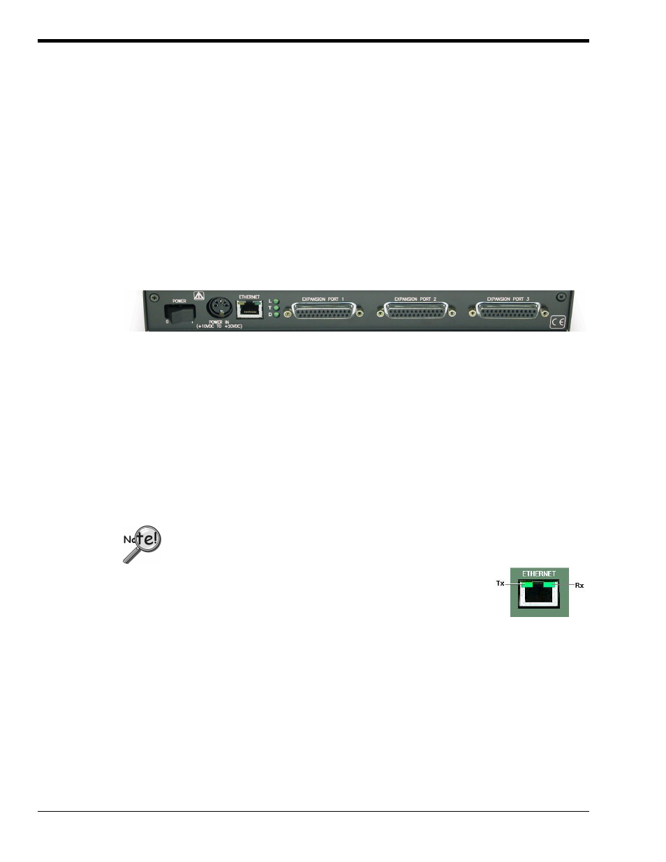
The WBK25 rear panel includes a power switch, DIN5 power in connector, Ethernet port, 5 LEDs
(2 of which are on the Ethernet port), and three parallel ports. These items are described below, in order
as they appear from left to right.
WBK25, Rear Panel
POWER Switch: A rocker-type switch with a “0” label for Power Off, and a “1” for Power On.
DIN5 POWER IN: +10 to +30 VDC, through a socket type DIN5 connector on the chassis. Power is
typically supplied from a TR-40U power adapter.
ETHERNET: The 10/100BaseT Ethernet port can connect to the Ethernet port of the host PC, or to an
Ethernet network. Either of two Ethernet patch cables may be used to make the connection. CA-242 is
a
1.5-foot long cable. CA-242-7 is a 7-foot long cable. Note that the Ethernet connector has two built in
LEDs (Tx and Rx) that indicate traffic flow. These are discussed with the three other Ethernet-related
LEDs.
To be CE compliant, the length of the Ethernet cable can not exceed 10m.
LEDs: There are 5 ETHERNET Status LEDS. Two rectangular LEDs (Tx and
Rx) are built into the frame of the Ethernet port. The other three LEDs,
located just to the right of the Ethernet port, are round and are labeled
L, T, and D for Link, BaseT, and Duplex, respectively.
Tx – “ON” indicates traffic is being transmitted (see following figure).
Rx – “ON” indicates that the port is receiving traffic.
L (Link) “ON” indicates a link exists. “OFF” indicates no link.
T (BaseT) “ON” indicates 100BaseTx; “OFF” indicates 10BaseT.
D (Duplex) “ON” indicates full duplex, which allows simultaneous
two-way data traffic. “OFF” indicates half-duplex, which
only allows one-way data traffic at any given time.
Tx and Rx LEDs
EXPANSION PORTS 1, 2, and 3: The three parallel ports are used to expand the system with up to
three additional devices. Each of these ports can be connected to the parallel port of a WaveBook/512A,
/516, /516A, DaqBook/2000A, DaqBook/2000X, WBK40, or a WBK41 via a CA-35-2 (2-foot) or a
CA-35-12 (1-foot) cable.
WBK25, pg. 2
919896
WBK25 Ethernet Interface Module User’s Guide
