Using the 2-pole filter and bypass – Measurement Computing WBK Options User Manual
Page 126
Using the 2-pole Filter and Bypass
2-pole Filter Mode
For applications where the signal of interest is entirely AC in nature, the low-pass filter mode of 8-pole is
the best choice. Vibration signals coupled through an ICP accelerometer are an example of this. However,
for applications where the DC component of the input signal is also of importance, 2-pole mode may
provide better results. Proximity sensor measurements are an example of this. This is because the 8-pole
switched capacitor filter, while providing excellent attenuation characteristics, does not process DC signals
with a high level of accuracy. For accelerometer applications this is not a limitation, as there is no
information in the DC component of the input signal. The 2-pole filter, in contrast, is formed by two 1-
pole RC filters in series. This filter provides excellent passband accuracy, at the expense of a more gradual
roll-off characteristic, as detailed below.
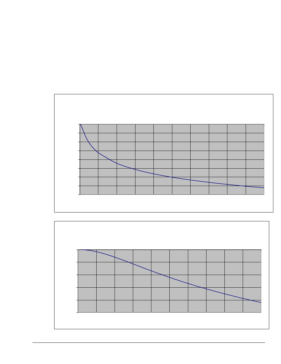
Gain of 2-pole Filter Mode
-80
-70
-60
-50
-40
-30
-20
-10
0
0
10
20
30
40
50
60
70
80
90
100
FIN/FC
Gain (dB)
Gain of 2-pole Filter Mode
-25
-20
-15
-10
-5
0
0
0.5
1
1.5
2
2.5
3
3.5
4
4.5
5
Gain (dB)
FIN/FC, Zoom-In to
Filter Cutoff Frequency Region
WBK18, Dynamic Signal Input Module
926896
WBK18, pg. 11