Caveats, Installation caution – Measurement Computing WBK Options User Manual
Page 58
Caveats
Transducers and load cells, most often employ full bridges with four active strain gages to benefit from
inherent temperature compensation and maximum output signal levels.
The mV/V sensitivities vary from unit to unit, but series resistors may be placed in the excitation lines to
adjust them into a particular range window. This technique makes externally connected shunt calibration a
little less exacting if the shunt resistor is not connected directly across the desired bridge arm. A shunt
calibration resistor provided internally by the transducer manufacturer will usually require connection to an
externally accessible node to activate the shunt. The variations in connection requirements require the
flexibility of a non-committed dry contact as provided by the WBK16/LC module.
Shunt calibration generally is done by shunting one arm of a bridge with four active arms. For this reason,
it is recommended that simulated signal levels be limited to about 20% of the full-scale output of the
transducer. Attempting to achieve a high level output with a single resistor will introduce non-linearity
errors into the picture. For example, a 5000 pound load cell should be shunt calibrated with a resistance
that will introduce about a 1000 pound output signal. Attempting to produce a 4000 pound signal by
shunting one of the bridge legs will generally not produce the same quality result.
Installation
CAUTION
Remove the WBK16 module from power and disconnect the unit from all externally
connected equipment prior to connecting cables, signal lines, and/or removing the
cover to install or remove components. Electric shock or damage to equipment can
result even under low-voltage conditions.
Take ESD precautions (packaging, proper handling, grounded wrist strap, etc.)
Use care to avoid touching board surfaces and onboard components. Only handle
boards by their edges (or ORBs, if applicable). Ensure boards do not come into
contact with foreign elements such as oils, water, and industrial particulate.
Be careful to avoid component damage while the WBK16 is open. Always remove the
WBK16/LC from the unit before soldering resistors.
You can easily install a WBK16/LC as follows:
Note: If a shunt calibration resistor is to be mounted on the WBK16/LC it should be done prior to the
installing the WBK16/LC. Shunt calibration resistors should be soldered in location R1 on the
WBK16/LC.
1. Review the preceding CAUTIONS.
2. Remove the StrainBook [or WBK16] from power and disconnect the unit from all external
devices and signals.
3. Observe proper ESD precautions.
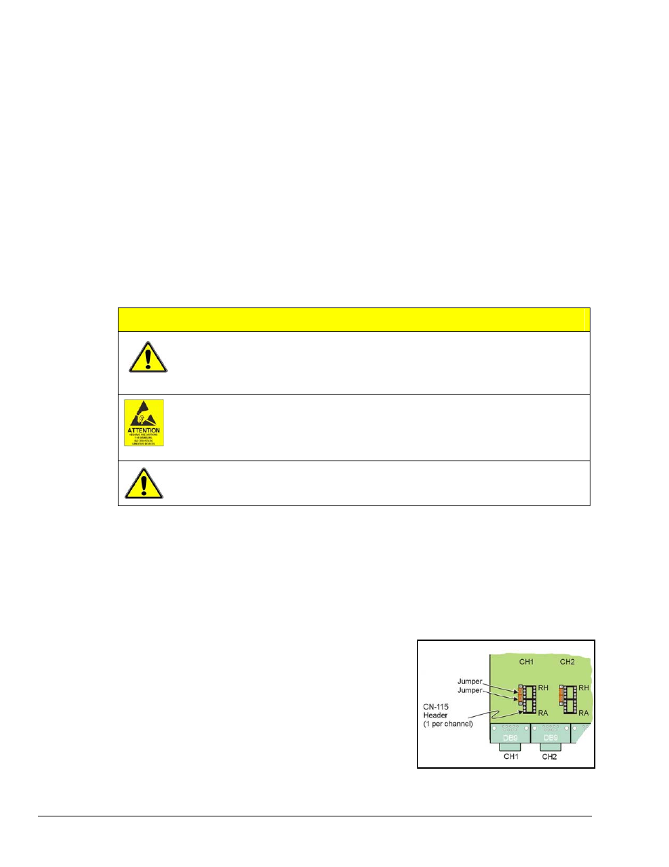
CN-115 Headers for CH1 and CH2
4. Remove the cover from the StrainBook [or WBK16].
5. Locate the CN-115 channel header(s) in which the
WBK16/LC modules are to be installed.
6. Remove one shunt jumper from each of the two
3-pin headers. The 3-pin headers are located beside
the CN-115 16-pin header sockets (see figure).
7. Remove the CN-115-1 (or CN-115) to expose the
header socket.
8. Carefully plug the module into the header socket.
9. Re-install the cover to the StrainBook [or WBK16].
WBK16, pg. 18
949794
WBK16, Strain-Gage Module