Measurement Computing WBK Options User Manual
Page 60
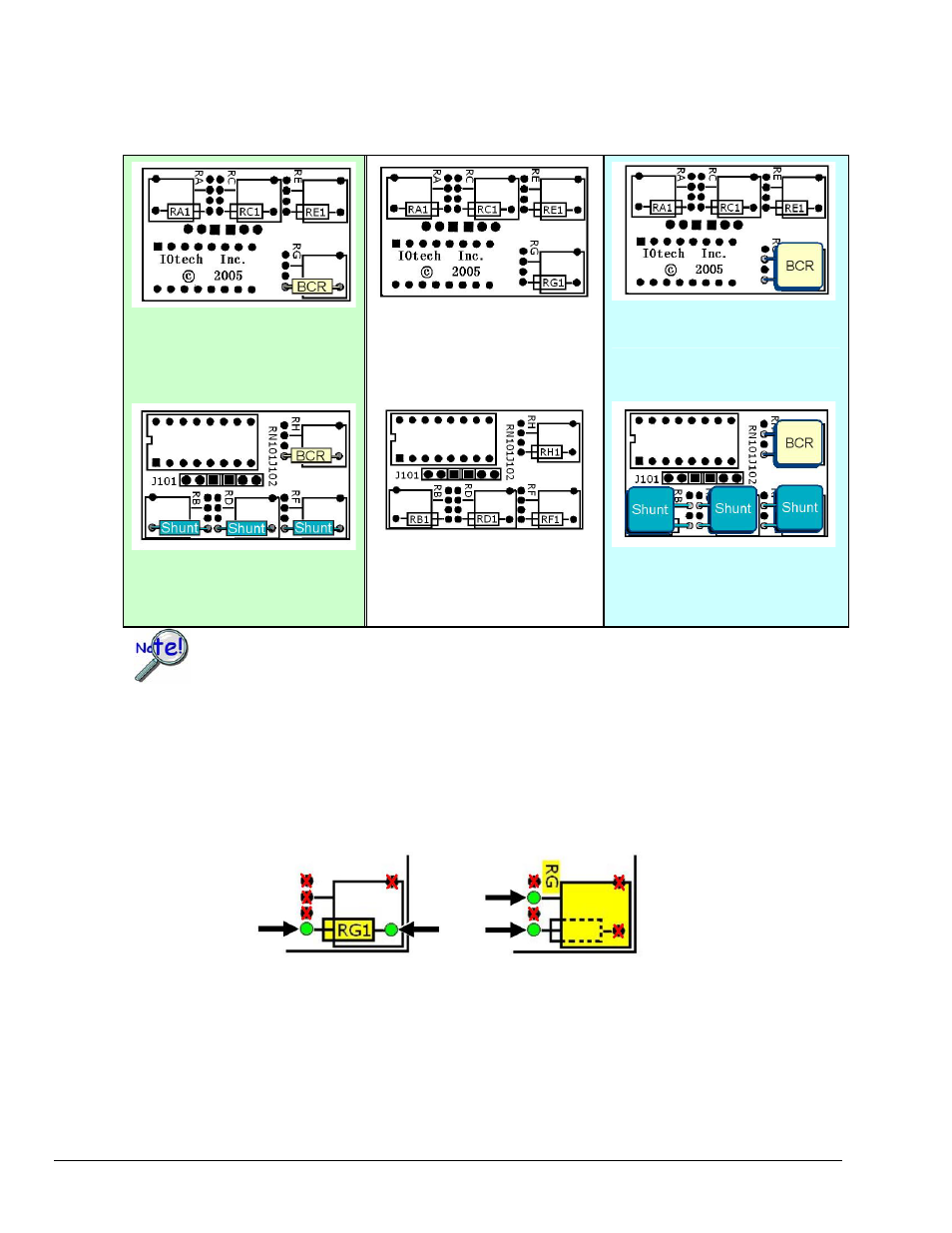
In the example below CN-115-1 is being used to create a half-bridge configuration with two Bridge Completion
Resistors (BCRs) and three Shunt resistors. The half-bridge to the left (using standard resistors) is functionally the
same as the half-bridge on the right (using “precision” resistors). The center illustration represents an unpopulated
card to permit reading of the silk-screen.
WBK16, pg. 20
949794
WBK16, Strain-Gage Module
For the functions listed in the preceding table, internal WBK16 configurations
still apply as indicated on pages 8 through 12 .
Using Standard Resistors
BCR at “RG1”
[Top Side of Card]
Shown Unpopulated
[Top Side of Card]
Using Precision Type Resistor
BCR at “RG” [Top Side of Card]
Using Standard Resistors
BCR at “RH1”
Shunts at “RB1” “RD1” “RF1”
[Plug-In Side of Card]
Shown Unpopulated
[Plug-In Side of Card]
Using Precision Type Resistors
BCR at “RH”
Shunts at “RB” “RD” “RF”
[Plug-In Side of Card]
How to Interpret Resistor Connection Points
The CN-115-1 plug-in card’s silk-screen makes use of dual templates. For example, if we look at the RG / RG1
section [on the top side of the card] we will see a small resistor image “RG1” with lines connecting to two solder
points. Thus we know the connection points for standard resistors. If we are using a flat, relatively square
precision-type resistor we would look at the square “RG” portion of the template (right image in the following
figure) and ignore the RG1 image. We can see that the lower left solder point remains, however, the second point
has changed.
Determining Solder Points for Resistor Leads