Measurement Computing WBK Options User Manual
Page 45
A fan draws and exhausts air through vents in the WBK16 enclosure. To maintain
sufficient cooling it is important to keep the fan and vents free of obstruction.
Bridge Applications
WBK16 can accommodate many different strain-gage configurations. All strain-gage bridge configurations
consist of a 4-element network of resistors. The quarter, half or full designation of a strain gage refers to
how many elements in the bridge are strain-variable. A quarter-bridge has 1 strain-variable element; a half-
bridge has 2 strain-variable elements; and a full-bridge has 4 strain-variable elements.
Full-bridges generally have the highest output and best performance. Output signal polarity is determined
by whether the strain-variable resistance increases or decreases with load, where it is located in the bridge,
and how the amplifier inputs connect to it. Configuration polarity is not important in WBK16, due to an
internal software-selected inversion stage. This simplifies bridge configuration.
Each WBK16 channel has locations for five bridge-completion resistors. These BCR’s are for use with
quarter and half-bridge strain gages. The resistors make up the fixed values necessary to complete the
4-element bridge design.
A full-bridge gage requires no internal completion resistors, but they may still be installed for other
configurations in use. The additional resistors will be ignored when the software has selected full-bridge
mode. Both quarter- and half-bridge gages require an internal half-bridge consisting of header positions Rg
and Rh. The recommended minimum values are 0.1%, <5 PPM/
°C drift, 1 KΩ, and 0.25-watt resistors.
Lower values will dissipate more power and add heat. Values >1K
Ω will increase the amount of drift and
noise. The same value half-bridge resistors can be used for any resistance strain gage. This internal half-
bridge will be automatically selected by the software when needed.
Internal 1 M
Ω shunt resistors are used to avoid open circuits.
These resistors are not suitable for high-accuracy/low-noise applications.
A quarter-bridge gage additionally requires a resistor of equal
value to itself. Up to 3 different values may be installed
simultaneously in header positions Ra, Rc, Re. All of these
resistors are connected to the (-) excitation terminal. An external
jumper at the input connector determines which resistor is
utilized. Therefore, 3 different quarter-bridge values can be
supported without opening the enclosure. Each different value
bridge would simply have the jumper in a different location;
when the gage is plugged in, the proper resistor is then already
selected. Configurations with the completion resistor on the (+)
excitation are redundant, due to the internal inversion stage, and
not used.
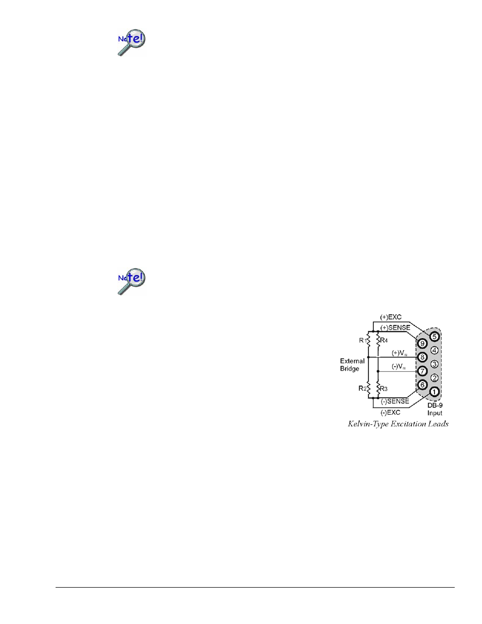
The bridge-configuration figures in the following text show various strain-gage configurations divided into
4 groups: Full-bridge, half-bridge, quarter-bridge, and high-gain voltmeter. Many of these configurations
can coexist but are shown individually for clarity.
WBK16, Strain-Gage Module
949794
WBK16, pg. 5