Ethernet ce kit, Ethernet ce kit installation instructions, P/n 1077-0901) – Measurement Computing WBK Options User Manual
Page 163: Introduction, Connect the ground line, Install the ferrite inductive collars
Ethernet CE Kit Installation Instructions
Introduction
The Ethernet CE Kit includes three ferrite clamp-on inductive collars to reduce EMI. It also includes a ground-line for
safety. The kit is simple to install and consists of the following components.
•
3 Ferrite Inductive Collars with Tie-wrap, p/n L-8-1
•
1 Ground-Line, p/n CA-250
•
4 Washers, #8 External Tooth, p/n WA-5 – used to lock screws (2 washers per screw)
•
1 Screw, #8-32x1/4 Phillips Pan-head, p/n HA-154-4 – used to secure the ground-line to a
threaded splice-plate hole on the data acquisition device
•
1 Screw, #6-32x5/16 Phillips Pan-head, p/n HA-2-5 – used to secure the ground-line to the PC
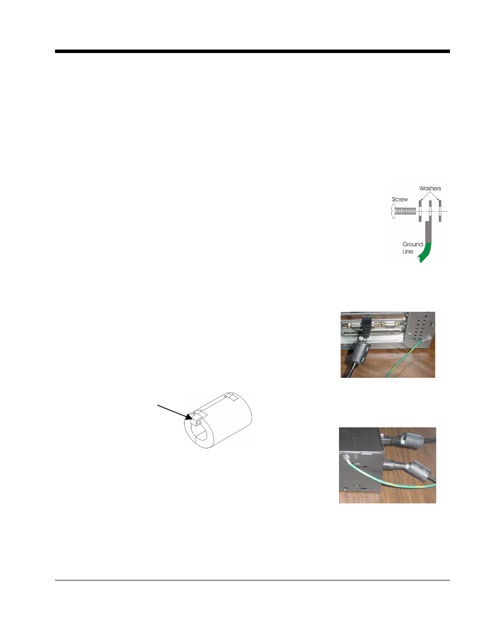
Connect the Ground Line
1. If using a desktop or tower PC, (a) remove a screw that secures the computer casing to
the chassis. The first photo shows a good connection point for the PC ground. (b) Use
the #6-32x5/16 screw and two #8 tooth washers, orientated as illustrated, to secure one
end of the ground line to the PC chassis.
If using a notebook (laptop) PC, connect one end of the ground-line to a known earth
ground. Depending on the ground chosen, you may need to use a screw other than the
one supplied.
2. On the data acquisition device, locate an available threaded splice-plate hole. This will
be used for attaching the ground line to the device, as indicated in the second photo.
3.
Use the #8-32x1/4 screw and two #8 tooth washers, orientated as illustrated, to secure
the free end of the ground line to the chassis of the data acquisition device. The second
photo shows such a connection.
Install the Ferrite Inductive Collars
1. Place one ferrite collar at each end of the Ethernet cable.
Snap the two collars shut. See photos.
2. Place the remaining ferrite collar next to the DIN5 connector on the
power cable. Snap the collar shut.
3.
Use a tie-wrap (one per ferrite collar) to secure each collar to its
respective cable.
This partial view of the host PC shows the
Ethernet cable with a ferrite collar. The
PC’s connection to the ground-line is also
visible.
Tie-wrap goes through
this opening.
4. (Optional) Trim the excess tie-wrap material. While trimming
use care to avoid cutting into the cables.
This completes the installation.
This partial view of the data acquisition
device shows its connection to the ground-
line. It also shows two ferrite collars, the
foremost of which is clamped to the power
cable. The background collar is clamped
onto the Ethernet cable.
928396
p./n
1077-0901
, rev
1.0