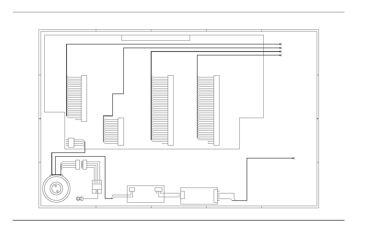
2 – thc control interface board (141088), 6 – wiring diagrams, Sheet 2 of 4 – Hypertherm THC ArcGlide User Manual
Page 246

246
ArcGlide THC Instruction Manual 806450
6 – Wiring Diagrams
2 – THC control interface board (141088)
5
5
4
4
3
3
2
2
1
1
D
D
C
C
B
B
A
A
Gray
Gray
Orange
Yellow
Black
Blue/White
White
White/Black
Black
Black
White
White
White/Black
Black
White
Black
Red
Black
White/Brown
White/Gray
White/Green
White/Orange
White/Violet
Orange
Green
White/Red
White/Black
Yellow
White/Yellow
Blue
White/Blue
Red
Black
Violet
White
Gray
Brown
Brown
Black
Black
Red
Black
White
Red
Green
Orange
Blue
White/Black
Red/Black
Green/Black
Orange/Black
Blue/Black
Black/White
Red/White
Green/White
Green
Orange
Green
Brown
Green
Yellow
Green
Blue
Green
White
Red
Orange
Red
Brown
Red
Yellow
Red
Blue
Red
Green
Red
White
Black
Orange
Black
Brown
Black
Yellow
Black
Blue
Black
Green
Black
White
Black
Red
Orange
Green
Brown
Green
Yellow
Green
Blue
Green
White
Red
Orange
Red
Brown
Red
Yellow
Red
Blue
Red
Green
Red
White
Black
Orange
Black
Brown
Black
Yellow
Black
Blue
Black
Green
Black
White
Black
Red
LIFTER INTERFACE
OP-CON INTERFACE
PLASMA INTERFACE
CNC INTERFACE
+5 VDC POWER
223007
100-pin Connector to Motor
Controller Processor PCB
014343
223001
223053
223003
Lifter Station Active
Encoder Common
NC (THC test)
Field Common (-)
Common (-)
Change Consumables Sw (+)
Lower Limit Sw (+)
Upper Limit Sw (+)
Breakaway Sw (+)
Lifter Up Sw (+)
Lifter Dwn Sw (+)
Encoder Input A (+)
Encoder Input A (-)
Encoder Input B (+)
Power +24 VDC
Ohmic Contact Sense Bias +12 VDC
Ohmic Contact Sense
Ohmic Contact Sense Common
Encoder Input B (-)
NC
Common (-)
Brake +
Motor -
Motor +
141134
Surge Board
AC/DC Power Supply
229234
Spare Output B
Manual Disable SwItch (+)
Manual Select Switch (+)
Torch Up Switch (+)
Torch Down Switch (+)
Spare Input Switch (+)
Common
Torch Enabled Output A
Error Output A
Spare Output A
Power +24 VDC Output
Torch Enabled Output B
Error Output B
Input Common (-)
Input Common (-)
Input Common (-)
Input Common (-)
Input Common (-)
Common
+24 VDC OUTPUT
Remote On Output A
Remote On Output B
Spare Input (+)
RS422 Tx+
RS422 Tx-
RS422 Rx+
RS422 Rx-
RS422 Common
Motion Input (+)
Error Input (+)
Rampdown Error Input (+)
Not Ready Input (+)
Corner Output B
Corner Output A
Pierce Output B
Pierce Output A
Hold Output B
Hold Output A
Start Output B
Start Output A
Spare Output B
Spare Output A
1/50 Arc Voltage (+)
1/50 Arc Voltage (-)
Cycle Start Input (+)
Low Gain Input (+)
IHS Sync Input (+)
Spare Input 1 (+)
Spare Input 2 (+)
IHS Complete Output A
Retract Complete Output A
Machine Motion Output A
THC Error Output A
Torch Breakaway Output A
CNC Spare Output A
Interlock Input (+)
Interlock Input (-)
Interlock Output A
Interlock Output B
Common
+24 VDC Fused Output
+24 VDC Output
+24 VDC Output
NC
NC
AVC Disable Input (+)
Common
Common
+24 VDC OUTPUT
+24 VDC OUTPUT
Reserved
NC
NC
Cycle Start Input (-)
Low Gain Input (-)
AVC Disable Input (-)
IHS Sync Input (-)
Spare Input 1 (-)
Spare Input 2 (-)
IHS Complete Output B
Retract Complete Output B
Machine Motion Output B
THC Error Output B
Torch Breakaway Output B
CNC Spare Output B
Common
Common
Common
223006
223005
223004
ArcGlide Motor Controller
Interface PCB
141088
J5
PLASMA INTERFACE
J5
PLASMA INTERFACE
1
2
3
4
5
6
7
8
9
10
11
12
13
14
15
16
17
18
19
20
21
22
23
24
25
26
27
28
29
30
31
32
33
34
35
36
37
J1
J1
1
2
1
2
3
1
2
3
4
5
6
J3
J3
1
2
3
4
5
6
7
8
J2
J2
1
2
3
EARTH GND
EARTH GND
1
1
2
3
4
J6
CNC INTERFACE
J6
CNC INTERFACE
1
2
3
4
5
6
7
8
9
10
11
12
13
14
15
16
17
18
19
20
21
22
23
24
25
26
27
28
29
30
31
32
33
34
35
36
37
Torroid Transformer
Torroid Transformer
J4
LIFTER INTERFACE
J4
LIFTER INTERFACE
1
2
3
4
5
6
7
8
9
10
11
12
13
14
15
16
17
18
19
20
21
22
23
24
AC Entry
AC Entry
A
B
C
D
GND
1
2
3
4
J7
OP-CON INTERFACE
J7
OP-CON INTERFACE
1
2
3
4
5
6
7
8
9
10
11
12
13
14
Sheet 2 of 4
