Jumpers – Gasboy CFN Site Controller User Manual
Page 17
Pump Interface Manual v1.3
Tokheim
9
03/20/03
Gasboy CFN Series
Jumpers
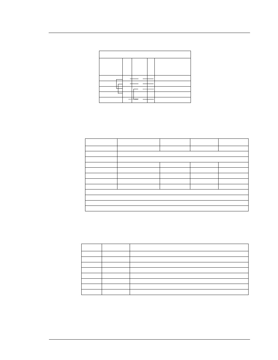
The jumpers for the DPT CPU are shown below. Additional information can be found in Section
7 of the Premier Technical Reference Manual, Tokheim Form #4817.
LEDs for the DPT CPU
The LEDs for the DPT CPU are shown in the following table. The LED will be on when the
described signal is active.
Switch settings
Each side of the Premier pump must have a different address and be set up individually as side A
or B. The switch settings for the DPT CPU are as follows:
Jumper
Description
Pins 1 & 2
Pins 2 & 3
Open
JU5
Watchdog*
Enables
√
Disabled
JU6
Normally open; when pins 1 & 2 are enabled, DPT enters diagnostics.
JU7
Normally open, AC low power detect is not used.
JU8
Battery**
Disabled
√
Enabled
JU9***
SC Communications
Half Duplex
√
JU10***
SC Communications
Half Duplex
√
Full Duplex
JU11***
SC Communications
Half Duplex
√
Full Duplex
JU12***
SC Communications
Full Duplex
Half Duplex
√
*Watchdog is the power supervision of the CPU board and should be enabled.
** The battery is the DPT CPU board RAM backup.
*** These jumpers configure the CPU board for full or half duplex.
√
Indicates the correct setting for GASBOY DPT interface.
LED
Color
Function
LED1
Red
Serial data is being received by the DPT from the cash acceptor
LED2
Green
Serial data is being transmitted by the DPT to the cash acceptor
LED3
Red
Diagnostic test signal defined by software
LED4
Red
Receive signal (RS-422/485) site controller port J4
LED5
Green
Transmit signal (RS-422/485) site controller port J4
LED
Red
Receive signal (RS-485) UDC port J5
LED7
Green
Transmit signal (RS-485) UDC port J5
LED8
Yellow
+5VDC logic power
Two wire wiring
RS422/
485
J-box
69
box
Tokheim
Premier
Tx+ 1
2
White
Tx-
2
1
Red
Rx+
3
3
Black
Rx-
4
Prot Gnd
5
4
Shield