1 control interfaces, 2 digital status circuits – Comtech EF Data HPCST-5000 User Manual
Page 79
High-Power TWTA Satellite Terminals
Single Thread System Installation
Rev.1
2–33
2.4.2.1.1 Control Interfaces
1.
High Voltage Select ON (Pin 2). Momentarily connect Pin 2 to ground (Pin 4) to
latch the High Voltage Select relay in the ON state. Return = Pin 4.
2.
High Voltage Select OFF (Pin 3). Momentarily connect Pin 3 to ground (Pin 4)
to release the latch of the High Voltage Select relay and set it to the OFF state.
Return = Pin 4.
3.
External Interlock (Pin 5). This circuit is designed for normally closed operation
(Pin 5 connected to Pin 4). Opening this circuit disables High Voltage ON. Open
circuit voltage is 15 VDC. The circuit is current limited to less than 1 mA when
shorted. Return = Pin 4.
4.
Fault Reset (Pin 6). Momentarily connect Pin 6 to ground (Pin 4) to reset latched
faults. Return = Pin 4.
Note: Activating the Beam Select OFF command line, followed by activating the
Beam Select ON command line, will also clear latched faults.
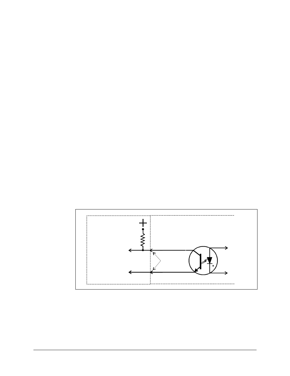
2.4.2.1.2 Digital Status Circuits
The digital status interface circuits are isolated outputs as shown in Figure Chapter 2-11.
EXTERNAL CIRCUITS
INTERNAL CIRCUITS
STATUS LINE
RETURN
STATUS LINE
PHOTO-COUPLER
Pair of I/O
Connector
Pins for Each
Status Circuit
Customer Supplied
Pull-Up Resistor
and 5-15 VDC
Figure Chapter 2-11. Digital Status Circuit Isolation
Note: The term “active = low” is used in the following paragraphs to indicate when a
condition is true and the status indicator is active (e.g., the photo-diode is conducting).