4 external connections – Comtech EF Data HPCST-5000 User Manual
Page 62
Single Thread System Installation
High-Power TWTA Satellite Terminals
2–16
Rev.1
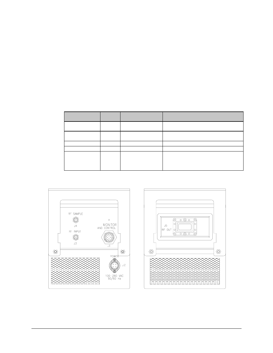
2.3.4 External Connections
Connections between the TWTA and other equipment are made through five connectors.
These connectors are listed in Table Chapter 2-1, and their locations are shown in Figure
Chapter 2-2 and Figure Chapter 2-3.
The use of each connector is described in the following paragraphs.
Table Chapter 2-1. External Connections
Name
Ref.
Design.
Connector
Type
Function
MONITOR AND
CONTROL
J1
PT06E-18-32S (SR)
Remote interface
POWER
J2
T3109-013
Prime power:
115 VAC; 230 VAC, 47 to 63 Hz
RF INPUT
J3
N, female
TX RF input, 50
Ω
input impedance
RF SAMPLE
J4
N, female
Calibrated reference
RF OUT
J5
WR-75G
TX RF output:
C-band (5845 to 6425 MHz)
Extended C-band (6725 to 7025 MHz)
Ku-band (14.0 to 14.5 GHz)
Figure Chapter 2-2. 100W and 140W TWTA External Connections