Figure chapter 2-10. interface connector pinouts – Comtech EF Data HPCST-5000 User Manual
Page 78
Single Thread System Installation
High-Power TWTA Satellite Terminals
2–32
Rev.1
Table Chapter 2-6. Remote Control Interface Connector Pinouts
Type
Pin #
Function
Return
Pin #
Comment
Control Interfaces
(All circuits are
active LOW)
2
3
5
6
High Voltage Select ON Control
High Voltage Select OFF Control
External Interlock
(see Note below)
Fault Reset Control
4
4
4
4
Pin 4 tied to Pin 16.
Digital Status Circuits
(All circuits are
active LOW)
8
10
12
21
23
25
High Voltage ON Status Indicator
Summary Fault Indicator
High Voltage Select ON Indicator
Standby Status Indicator
FTD (Filament Time Delay)
Remote/Local Indicator
7
22
24
9
11
13
Pins 7, 9,11, and 22 tied together.
May be interchanged.
Analog Status Circuits
14
15
17
Helix Current Monitor
High Voltage Monitor
TWT Temperature Monitor
16
16
16
Pin 16 tied to Pin 4.
Output Voltage Circuits
1
19
+24 Volts DC
+15 Volts DC
16
16
Ground
4, 16
Common Ground (connected)
NA
Note: Pin 5 is connected to Pin 4 with an internal jumper.
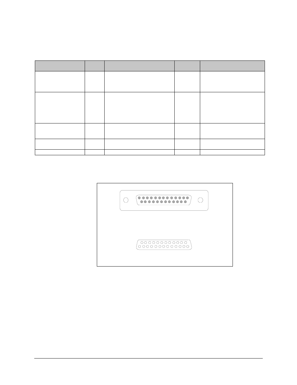
TWTA REMOTE CONTROL INTERFACE CONNECTOR
(MALE) DB-25(M)
MATING REMOTE CONTROL INTERFACE PLUG
(FEMALE) DB-25(F)
14
25
1
13
14
13
25
1
Figure Chapter 2-10. Interface Connector Pinouts