2 external connections, 1 external interfaces (j1) – Comtech EF Data HPCST-5000 User Manual
Page 77
High-Power TWTA Satellite Terminals
Single Thread System Installation
Rev.1
2–31
2.4.2 External Connections
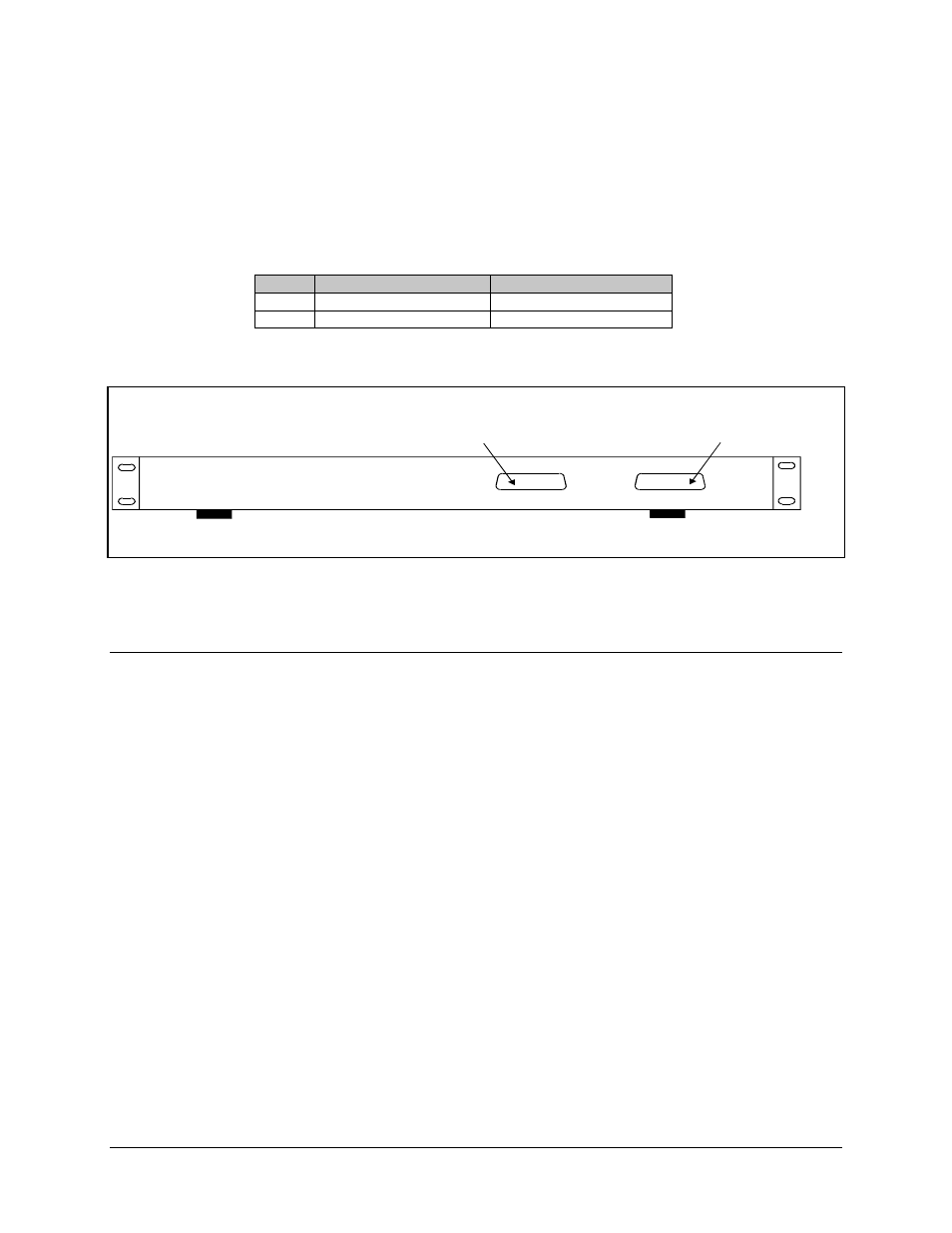
The HPC-1200 controller (Figure Chapter 2-9) provides for the following list of external
connections on the rear panel (Table Chapter 2-5):
Table Chapter 2-5. Rear Panel Connectors
Ref.
Name
Rear Panel Connector
J1
Remote Interface
D-type, 25 pin, male
J2
ODU Monitor & Control
D-type, 25 pin, female
J2
J1
O DU MONITO R & CO NTROL
J2 TO POW ER AMPLIFIER (FEM ALE DB-25)
J1 REM OTE CONTROL INTERFACE
REMO TE INTERFACE
Figure Chapter 2-9. HPC-1200 Rear Panel Connector Locations
2.4.2.1 External Interfaces (J1)
The HPC-1200 Remote Control Interface (J1) is MPS compatible. The interface
connector (J1) pinouts are described in Table Chapter 2-6 and shown in Figure Chapter
2-10.
All Control Command Inputs are static protected, opto-isolated inputs with internal pull-
up to +15V through 10k resistor. The external interlock is relay or switch contact closure
to the interlock return. All Status Indicator outputs are transient-protected, open collector
opto-isolated transistors with a minimum in-line series resistance of 100
Ω
.
Pins 4 and 5 must be connected to enable operation of the power supply. These pins have
been internally connected by the manufacturer.