3 “x” insert panel configurations – Comtech EF Data HPCST-5000 User Manual
Page 117
High-Power TWTA Satellite Terminals
Redundant System Installation
Rev. 1
3–33
Type
Pins
Functions
Control Commands
(All active low)
24
6
9
21
23
AC Power ON
High Voltage Enable
Heater Standby
Fault Reset
Not Applicable
Status Indicators, digital inputs
(unless specified, all active low)
1
3
7
8
10
12
15
16
17
18
20
Not Applicable
Not Applicable
Heater Timer Complete
Not Applicable
High Voltage ON
Not Applicable
Not Applicable
Not Applicable
Summary Fault
Not Applicable
Status Return
Status Indicators, analog outputs
4
11
13
14
2
25
Not Applicable
Not Applicable
VDC/Analog Return
Not Applicable
Not Applicable
Not Applicable
Input Voltages
5
19
+15 VDC (100 mA max.)
DC Power on Detect
External Voltage Input
22
Not Applicable
Not Used
26 to 37
Not Applicable
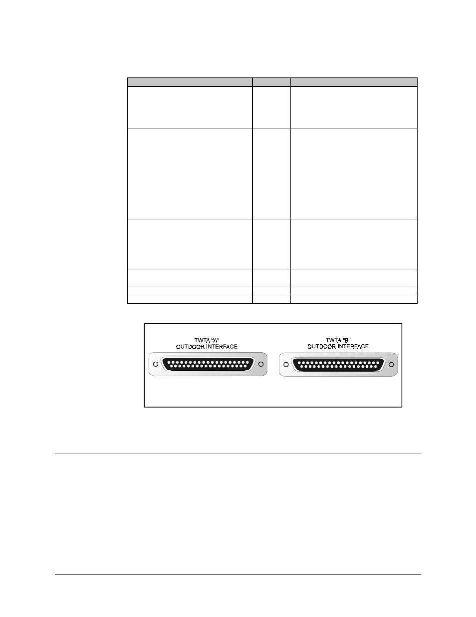
Figure 3-12. Auxiliary Interface Connector Pinouts
3.4.2.3 “X” Insert Panel Configurations
The configurations used for redundant systems incorporating rack-mounted TWTAs are
outlined in Figure 3-13.