Figure chapter – Comtech EF Data HPCST-5000 User Manual
Page 19
High-Power TWTA Satellite Terminals
Introduction
Rev. 1
1–3
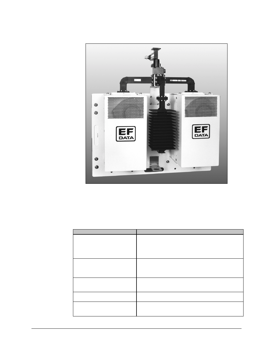
Figure Chapter 1-2. TWTA Redundant Assembly (Typical)
Refer to Table Chapter 1-2 for a typical HPKST-12000 redundant system.
Table Chapter 1-2. Major Assemblies of the HPKST-12000
Nomenclature
Description
Outdoor LNA Assy
Consists of a transit reject filter, redundant LNAs (120
°
K; 90
°
K
Optional) and a
Ku-Band waveguide switch. Optionally, a Ku-Band coaxial
switch, 1:4 power splitter, and frequency (block) converter are
available.
Outdoor KST-12000 Redundant
Assy
Consists of two RFT-12000 redundant assemblies. Each RFT
includes an up converter with a 70 MHz IF input, a down
converter with a 70 MHz IF output, an M&C microprocessor,
and a power supply.
Outdoor TWTA Redundant Assy
(Figure 1-2)
Consists of two high-power TWTAs, a waveguide switch, an
output coupler, and a system cable harness with a customer-
interface connector for system control.
HPS-1110
An optional indoor, rack-mounted, redundant TWTA controller.
Allows the customer M&C of TWTAA operations.
Redundancy Switch Unit (RSU)
Along with a redundancy cable/hardware kit, provides the system
with a single M&C interface, redundancy switchover, and
cabling.