2 external connections – Comtech EF Data HPCST-5000 User Manual
Page 111
High-Power TWTA Satellite Terminals
Redundant System Installation
Rev. 1
3–27
3.4.2 External Connections
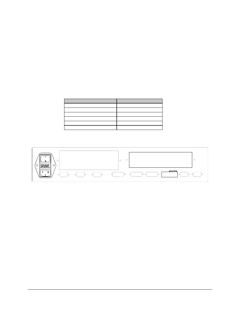
All connections are made at the rear panel of the controller (Figure 3-7). With the
exception of prime power, which should be connected last, the timing and sequencing of
the controller connections are not critical. However, the correct TWTA connectors must
be connected to the corresponding set on the rear panel of the controller.
The HPC-1110 provides for a discrete interface for monitor and control of the TWTA.
The HPC-1110 provides inputs for switch position indicators (2 pins and common). All
other connections are not used.
Name
Connector Type
Controller Prime Pwr AC
AC Plug
AUX TWTA “A” Aux Interface
D-type, 25 pin female
AUX TWTA “B” Aux Interface
D-type, 25 pin female
WG SW #1
D-type, 15 pin female
EIA-485 Remote Control
D-type, 9 pin male
EIA-232-C Remote Control
D-type, 9 pin male
TWTA "A"
TWTA "B"
TWTA "C"
EXTERNAL INTERLOCK
REMOTE FUNCTIONS
WAVEGUIDE
SWITCH "1"
ADDRESS
1 2 3 4 5 6 7 8 9 10
RS485
RS232
WAVEGUIDE
SWITCH "2"
"Y" Insert Panel
"X" Insert Panel
Figure 3-7. HPC-1110 Rear Panel