Basler Electric DECS-400 User Manual
Page 67
9369700990 Rev R
55
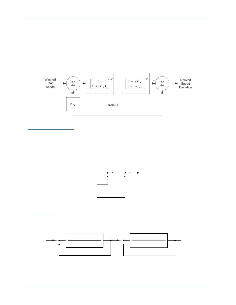
The derived integral of mechanical power signal is then passed through a mechanical-power, low-pass
filter and ramp tracking filter. The low-pass filter is controlled by time constant TI3 and provides
attenuation of torsional components appearing in the speed input path. TI3 has a setting range of 0.05 to
0.20 seconds with 0.01 second increments. The ramp tracking filter produces a zero, steady-state error to
ramp changes in the integral of electric power input signal. This limits the stabilizer output variation to very
low levels for the mechanical power rates of change that are normally encountered during operation of
utility-scale generators. The ramp tracking filter is controlled by time constant Tr. Tr has a setting range of
0.05 to 1 second with 0.01 second increments. The low-pass filter and ramp tracking filter time constants
are accessed on the Parameters tab of the BESTCOMS PSS screen.
Processing of the derived integral of mechanical power signal is illustrated in Figure 21.
Figure 21. Derived Mechanical Power Signal
Stabilizing Signal Selection
Figure 22 illustrates how software switches SSW 2 and SSW 3 are used to select the stabilizing signal.
Derived speed deviation is selected as the stabilizing signal when the SSW 2 setting is Derived Speed
and the SSW 3 setting is Derived Frequency/Speed. Washed out speed is selected as the stabilizing
signal when the SSW2 setting is Frequency and the SSW 3 setting is Derived Frequency/Speed. Washed
out power is selected as the stabilizing signal when the SSW 3 setting is Power. (When the SSW3 setting
is Power, the SSW 2 setting has no effect.) SSW 2 and SSW 3 are accessed on the Control tab of the
BESTCOMS PSS screen.
Figure 22. Stabilizing Signal Selection
Torsional Filters
Two torsional filters, shown in Figure 23, are available after the stabilizing signal and before the phase
compensation blocks. The torsional filters provide the desired gain reduction at a specified frequency. The
filters compensate the torsional frequency components present in the input signal.
Figure 23. Torsional Filters
Software switch SSW 4 enables and disables torsional filter 1 and SSW 5 enables and disables torsional
filter 2. SSW 4 and SSW5 are accessed on the Control tab of the BESTCOMS PSS screen.
P0026-19
12-09-04
Derived
Speed
Deviation
SSW 2
Washed
Out Speed
SSW 3
Stabilizing
Signal
Washed
Out Power
Stabilizing
Signal
2
2
2
2
2
2
n
n
d
n
n
n
w
s
w
z
s
w
s
w
z
s
+
+
+
+
2
2
2
2
2
2
n
n
d
n
n
n
w
s
w
z
s
w
s
w
z
s
+
+
+
+
Phase
Compensation
P0026-20
12-09-04
Disable
SSW 5
SSW 4
Enable
Disable
Enable
DECS-400
Functional Description