Pss theory of operation, Decs-400 functional description – Basler Electric DECS-400 User Manual
Page 65
9369700990 Rev R
53
PSS features include user-selectable speed-only sensing, two- or three-wattmeter power measurement,
optional frequency based operation, generator and motor control modes, and rate of frequency change
blocking.
PSS Theory of Operation
The PSS uses an indirect method of power system stabilization that employs two signals: shaft speed and
electrical power. This method eliminates the undesirable components from the speed signal (such as
noise, lateral shaft run-out, or torsional oscillations) while avoiding a reliance on the difficult-to-measure
mechanical power signal.
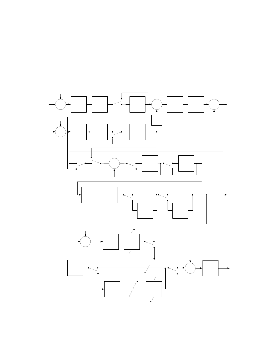
PSS function is illustrated by the function blocks and software switches shown in Figure 18.
Frequency
Washout Filter
2
Frequency
Washout Filter
1
SSW 0
Low-Pass
Filter
Enable
Disable
Σ
+
Mechanical
Power
Low-Pass
Filter
Ramp
Tracking Filter
Σ
+
Power
Washout
Filter 1
Power
Washout
Filter 2
SSW 1
Disable
Enable
Integrator
Power
Input
Scalar
+
SSW 2
Frequency
Derived
Speed
SSW 3
Derived
Freq./Speed
Power
SSW 4
Torsional
Filter 1
SSW 5
Torsional
Filter 2
Enable
Disable
Enable
Disable
Phase
Compensation
Stage 4
Phase
Compensation
Stage 3
Phase
Compensation
Stage 2
Phase
Compensation
Stage 1
SSW 6
Disable
Enable
SSW 7
Disable
Enable
Σ
_
Terminal
Voltage
Low-Pass
Filter
Ramp Limiter
–4%/s
+2%/s
+
V
PSS_SLMT
0
V
T_LMT
SSW 8
Disable
Enable
Gain Stage
Scale Factor
SSW 9
Disable
Enable
Logic Limiter
Washout Filter
Logic Limiter
Washout Filter
V
PSS_ULMT
V
PSS_LLMT
SSW 10
Enable
Disable
V
PSS_ULMT
V
PSS_LLMT
ω
DEV
V
PSS
PSS
Output
V
T
ω
COMP
P
E
P0053-36
_
lmt_hi
lmt_lo
Σ
+
+
Test signal input of
comp frequency
Σ
+
+
Test signal input of
electric power
Σ
+
+
Test signal input of
derived speed
Σ
+
+
Test signal input of
AVR summing
Figure 18. PSS Function Blocks and Software Switches
DECS-400
Functional Description