Figure 106, Decs-400 programmable logic, Figure 106. default logic – Basler Electric DECS-400 User Manual
Page 183
9369700990 Rev R
171
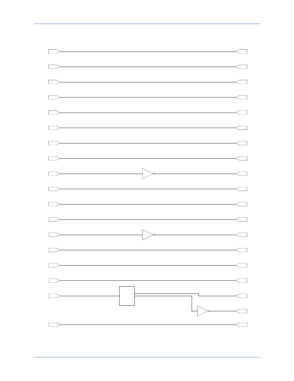
Figure 106. Default Logic
Start Input
Stop Input
AVR Input
Manual Input
Raise Input
Lower Input
Switch Input 1
Alarm Reset
Switch Input 2
Pre-Position #2
Switch Input 3
52L/M
Switch Input 4
Secondary DECS Select
Switch Input 5
Pre-Position #1
Switch Input 6
Sec. Prot. Settings Select
Switch Input 7
52J/K
Switch Input 8
Secondary PID Select
Switch Input 9
PSS Enable
Switch Input 10
Sec. PSS Settings Select
Load Comp. Status
0=Off-Line, 1=On-Line
Start Initiate
Stop Initiate
AVR Initiate
Manual Initiate
Raise Setpoint Initiate
Lower Setpoint Initiate
Alarm Reset Initiate
Pre-Position #2 Initiate
Parallel Mode Activate
Auto-Transfer Enable
Pre-Position #1 Initiate
Secondary Protection
Settings Enable
Var/PF Mode Activate
Secondary PID Select
PSS Control Enable
Secondary PSS
Settings Select
OEL Option
0=Off-Line, 1=On-Line
Voltage Matching
0=Disabled, 1=Enabled
Layer 1, Gate 1
Layer 1, Gate 2
Layer 1, Gate 3
u
2
u
3
u
4
u
1
x
1
MUX
u
4
u
4
Layer 1, Gate 1
P0070-40
Fixed Logic
FALSE #10
Manual FCR Only
DECS-400
Programmable Logic