Basler Electric DECS-400 User Manual
Page 155
9369700990 Rev R
143
•
The generator voltage should build to a percentage of the rated voltage. (The FCR
setpoint was set to 20% of the rated exciter field current in a previous step.) ...................... ________
•
Increase the exciter field current to 75% of rated. ................................................................. ________
•
The generator voltage should build to a percentage of the rated voltage. ............................ ________
•
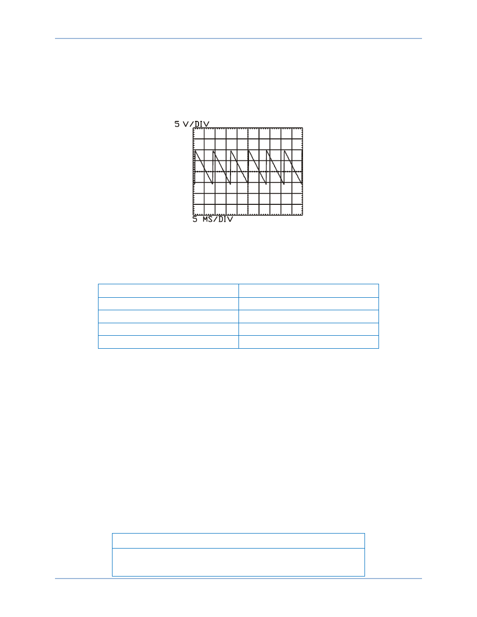
Check the field voltage with an oscilloscope to verify proper output. (See the current
balance firing circuit waveform of Figure 103.) ...................................................................... ________
Figure 103. Field Voltage Output Waveform
•
Meter for the correct voltages at the voltage sensing inputs (E1, E2, E3). ........................... ________
•
Measure the PPT secondary voltages. (See Table 22 for the correct secondary
voltages at the transformer output.)
Table 22. PPT Secondary Voltages
Rectifier DC Voltage
PPT AC Secondary Voltage
63
80
125
160
250
360
375
480
•
Using the Raise/Lower control raise the terminal voltage incrementally to the rated
voltage. .................................................................................................................................. ________
•
Place the Start/Stop switch in the Stop position. ................................................................... ________
•
Place the Start/Stop switch in the Start position to start the generator in FCR mode. .......... ________
•
Record the voltage buildup characteristic of the system as it reaches full-rated output. ...... ________
•
Perform a step response in FCR mode. ................................................................................ ________
•
Using the BESTCOMS Analysis screen, perform a 5% step change in FCR mode. ............ ________
•
Decrease the value first, and then increase the value. (Observe stable performance
using the recording capabilities of the Analysis screen.)....................................................... ________
•
Note the overshoot and settling time. (The FCR output should be very stable.) .................. ________
During the following test, be prepared to transfer back to FCR mode if there is a problem. Use the
BESTCOMS Metering screen to verify that tracking is stable before transferring. The Null Balance
indicator on the front panel should be continuously lit. If pre-position is enabled, the setpoint will go to the
assigned value first. Pre-position may need to be disabled for this test.
•
Verify that the AVR setpoint follows (auto-tracks) the FCR setpoint, then transfer. ............. ________
Note
During the following test, if pre-position is enabled, the setpoint will go
to the assigned value first.
DECS-400
Commissioning