Human-machine interface, Controls and indicators – Basler Electric DECS-400 User Manual
Page 21
9369700990 Rev R
9
Human-Machine Interface
This chapter describes the DECS-400 human-machine interface (HMI) and illustrates navigation of the
menu tree accessed through the front panel and LCD.
Controls and Indicators
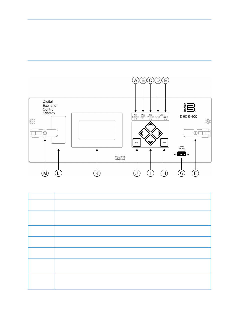
DECS-400 controls and indicators are illustrated in Figure 2 and described in Table 1. The locators and
descriptions of Table 1 correspond to the locators shown in Figure 2.
Figure 2. Controls and Indicators
Table 1. Control and Indicator Descriptions
Locator
Description
A
Null Balance Indicator. This LED lights when the setpoint of the inactive operating
modes (AVR, FCR, Var, or Power Factor) match the setpoint of the active mode.
B
PSS Active Indicator. This LED lights when the integrated power system stabilizer is
enabled and can generate a stabilizing signal in response to a power system
disturbance.
C
Pre-Position Indicator. This LED lights when the setpoint of the active operating mode is
at either of the two pre-position setting levels.
D
Lower Limit Indicator. This LED lights when the setpoint of the active operating mode is
decreased to the lower setpoint limit.
E
Upper Limit Indicator. This LED lights when the setpoint of the active operating mode is
increased to the upper setpoint limit.
F
Latch. Two lever-style latches (locators F and M) secure the DECS-400 draw-out
assembly in its case. A captive Phillips screw in each latch can be tightened to lock the
draw-out assembly in place.
G
Communication Port. This RS-232 port has a female DB-9 connector for local
communication with a PC operating BESTCOMS software (supplied with the DECS-
400).
DECS-400
Human-Machine Interface