Fie l d cu r re nt time in seconds – Basler Electric DECS-400 User Manual
Page 57
9369700990 Rev R
45
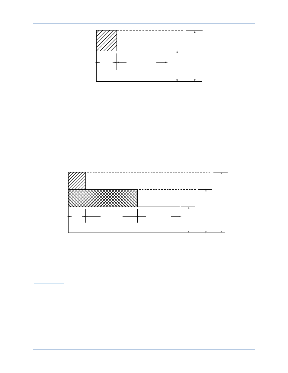
Figure 12. Summing Point, Off-Line Overexcitation Limiting
There are three sets of summing point OEL settings for on-line operation: a high-level setting, a medium-
level setting, and a low-level setting. Figure 13 illustrates the relationship of the high-, medium-, and low-
level settings. The high-level, on-line OEL threshold is determined by the On-Line High Level and On-Line
High Time settings. The On-Line High Level setting has a setting range of 0 to 11,999 Adc with 0.01 Adc
increments. The On-Line High Time setting has a setting range of 0 to 60 seconds with 1 second
increments. The medium-level, on-line threshold is determined by the On-Line Medium Level and On-Line
Medium Time settings. The On-Line Medium Level setting has a setting range of 0 to 11,999 Adc with
0.01 Adc increments. The On-Line Medium Time setting has a setting range of 0 to 120 seconds with 1
second increments. The low-level, on-line OEL threshold is determined by the On-Line Low Level setting,
which serves as an annunciation that on-line excitation is at an elevated level. The generator is permitted
to operate indefinitely at the On-Line Low Level setting. The On-Line Low Level setting has a setting
range of 0 to 11,999 Adc with 0.01 Adc increments.
Figure 13. Summing Point, On-Line Overexcitation Limiting
On-line OEL operation can be tailored for fault proximity by OEL Voltage Dependency (dv/dt Enable and
dv/dt Level) settings in BESTCOMS. If a fault is close to the generator, the OEL high-level setting is
disabled (based upon the rate of change) and switches to the medium-level, summing-point OEL setting.
If the fault is away from the machine, all three (high, medium, and low) settings are active.
Takeover OEL
There are two sets of takeover OEL settings for off-line and on-line operation: a low-level setting and a
high-level setting. The field current level at which limiting occurs is determined by an inverse time
characteristic similar to that shown in Figure 14. Separate curves may be selected for on-line and off-line
operation. If the system enters an overexcitation condition, the field current is limited and made to follow
the selected curve.
F
IE
L
D
CU
R
RE
NT
TIME IN SECONDS
High
Current
Time
CONTINUOUS
D2851-18.vsd
04-03-01
0-10sec
Low
Current
Level
0-15Adc
High
Current
Level
0-30Adc
F
IE
L
D
CURRE
NT
TIME IN SECONDS
High
Current
Time
0-10sec
CONTINUOUS
D2851-17.vsd
04-03-01
Medium
Current
Time
0-120sec
Low
Current
Level
0.0 - 15 Adc
Medium
Current
Level
0.0 - 20 Adc
High
Current
Level
0.0 - 30Adc
DECS-400
Functional Description