Message framing and timing considerations, Error handling and exception responses – Basler Electric DECS-400 User Manual
Page 217
9369700990 Rev R
205
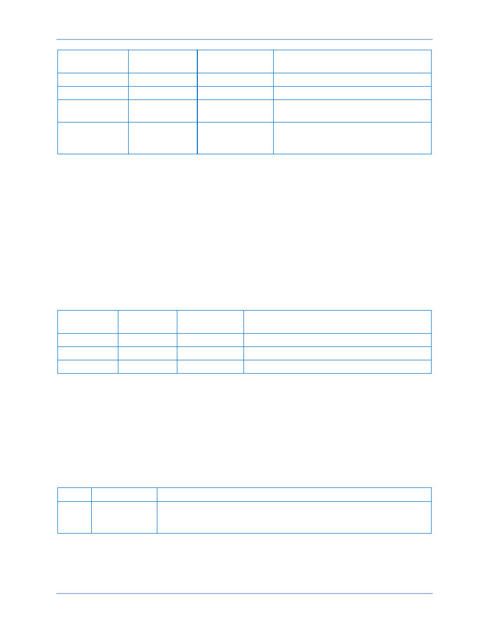
Setting
Programmable
Y (Yes)/N (No)
Default Value
Value Range
Parity
Y
None
‘N’=None, ‘O’=Odd, ‘E’=Even
Stop Bits
Y
2
1 or 2
Modbus Slave
Address
Y
247
0 for broadcast, 1 to 247 for slave
Modbus
Response Delay
Time (in ms)
Y
10 ms
From 0 to 200 ms in increments of 10 ms
Communication settings are user-selectable and can be set at installation and altered during real-time
operation.
Message Framing and Timing Considerations
When receiving a message, the DECS-400 requires an inter-byte latency of 3.5 character times before
considering the message complete.
Once a valid query is received, the DECS-400 waits an amount of time as specified in the Modbus
Response Delay Time Register (48108) before responding. This register contains a value from 0 to 200
milliseconds. The default value is 10 milliseconds. The user may set the remote delay time parameter to 0
to minimize response latency.
Table 26 provides the response message transmission time (in milliseconds) and 3.5 character times (in
milliseconds) for the maximum response message length (225 characters), response to a read query for
125 points, and various baud rates.
Table 26. Timing Considerations for 10 Character Bits (8 Data Bits + 1 Start Bit + 1 Stop Bit)
Baud Rate
1 character
Time (ms)
3.5 characters
Time (ms)
Max. Read Register Response Message
(255 characters) Transmission Time (ms)
4800
2.083
7.292
531.165
9600
1.0417
3.645
265.6335
19200
0.52083
1.823
132.812
Error Handling and Exception Responses
Any query received that contains a nonexistent device address, a framing error, or CRC error is ignored.
No response is transmitted. Queries addressed to a DECS-400 with an unsupported function code,
unsupported register references, or illegal values in the data block result in an error response message
with an exception response code.
Each error response message consists of a slave (DECS-400) address, function code with the high-order
bit set, error code, and error check (CRC) field.
The exception response error codes supported by the DECS-400 are provided in Table 27.
Table 27. Supported Exception Response Codes
Code
Name
Meaning
01
Illegal Function
The query Function/Sub-function Code is unsupported; query read of more
than 125 registers; query “preset multiple registers” of more than 100
registers
DECS-400
Modbus™ Communication