16 clock structure, 17 reset structure, 16 clock structure 4.17 reset structure – Artesyn MVME2500 ECC Installation and Use (August 2014) User Manual
Page 82: Figure 4-3, Clock distribution diagram
Functional Description
MVME2500-ECC Installation and Use (6806800N30F)
82
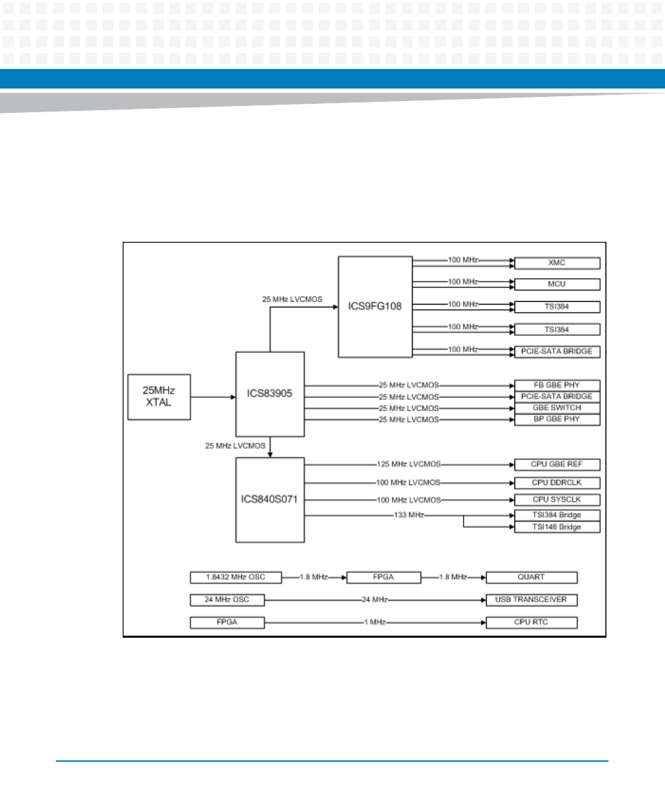
4.16 Clock Structure
A total of three IDT chips, a discrete oscillator and crystal to support all the clock requirements
of MVME2500-ECC.
4.17 Reset Structure
MVME2500-ECC reset will initiate after the power up sequence if the 1.5 V power supply is
"GOOD". When the board is at "ready" state, the reset logic will monitor the reset sources and
implement the necessary reset function.
Figure 4-3
Clock Distribution Diagram