Functional description, 1 block diagram, 2 chipset – Artesyn MVME2500 ECC Installation and Use (August 2014) User Manual
Page 67: 1 block diagram 4.2 chipset, Figure 4-1, Block diagram, Chapter 4, functional description, Chapter 4
Chapter 4
MVME2500-ECC Installation and Use (6806800N30F)
67
Functional Description
4.1
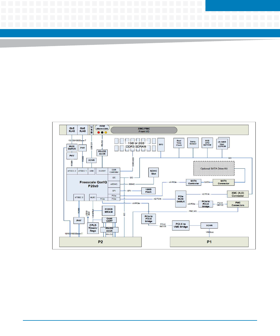
Block Diagram
The MVME2500-ECC block diagram is illustrated in
. All variants provide front panel
access to one serial port via a micro-mini DB-9 connector, two 10/100/1000 Ethernet port
(one is configurable to be routed on the front panel or to the rear panel) through a ganged RJ45
connector and one Type A USB Port. It includes Board Fail LED indicator, user-defined LED
indicator and a ABORT/RESET switch.
4.2
Chipset
The MVME2500-ECC utilizes the QorIQ P20x0 integrated processor. It offers an excellent
combination of protocol and interface support including dual high performance CPU cores, a
large L2 cache, a DDR2/DDR3 memory controller, three enhanced three-speed Ethernet
controllers, two Serial RapidIO interfaces with a messaging unit, a secure digital interface, a
USB 2.0 interface and three PCI express controllers.
Figure 4-1
Block Diagram